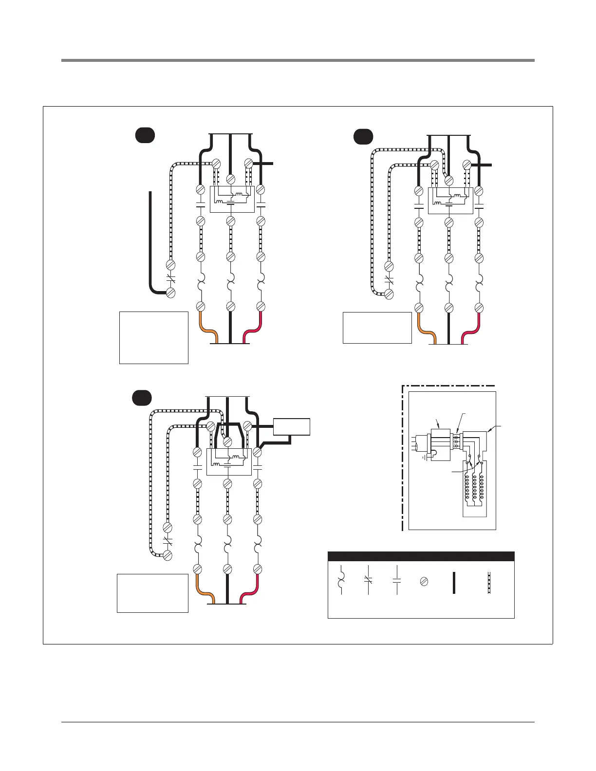
Figure 25. Three Phase Pump Wiring Diagram Examples
Orange RedBlack
T1
L1
L1 L2 L3
L2
L3
X2
T2 T3
To CSTP by Installer
(see diagram lower right)
To CSTP by Installer
(see diagram lower right)
To Power Supply by Installer
To CSTP by Installer
(see diagram lower right)
To Power Supply by Installer
To Power Supply by Installer
To
Neutral
To Isotrol
220/240 V
isolated
output
NOTE: Coil above is wired
for 400 V to pump motor,
230 V from Isotrol or
dispenser switch.
(Remove red wire
connecting X2 to L2)
COIL
3 421
3
153/fig25.eps
LEGEND
Overload
heater
Normally
closed
contact
Normally
open
contact
Screw
terminal
Wire added
by installer
Wire added
by manufacturer
A
Orange RedBlack
T1
L1
L1 L2 L3
L2
L3
X2
T2 T3
To Neutral
(Dispenser)
NOTE: Coil above is wired
for 400 V to pump motor,
230 V to dispenser switch.
COIL
3 421
3
B
Orange RedBlack
T1
L1
L1 L2 L3
L2
L3
X2
T2 T3
Dispenser
NOTE: Coil above is wired
for 400 V to pump motor,
400 V to dispenser switch.
(Rewire red wires at coil).
COIL
3 421
3
C
Electrical
interlock
Internal
overload
protectors
Extractable
packer
Conduit/contractors
box attached
to manifold
Motor
R
O
G
STP