Redback Technologies
Owner’s Guide – Redback Smart Hybrid System - v 3.8
27
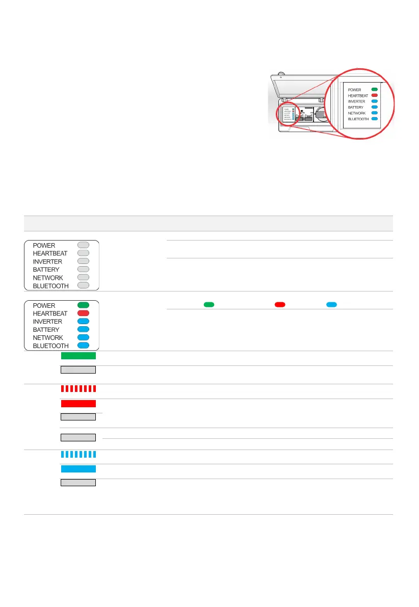
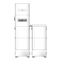
12.6 EMS Status LEDs
The EMS controls the inverter functionality, and all internal and external
communications. The EMS a.k.a. Control Board is located inside the Balance of
System (BoS). The EMS Status LEDs are visible in the BoS Switchgear Hatch.
The table below lists EMS LED indications, probable causes, and rectification
steps you can try yourself. Refer to page 9 to identify controls.
If the problem is not solved contact your installer for assistance.
A note about EMS Labels
In 2018, the EMS LED labels were updated: the unused 4G LED was repurposed for Bluetooth notification, and the Wi-Fi LED
was renamed to Network. There were no other changes to the EMS.
In this document “Network LED” means the Network LED or the Wi-Fi LED, and “Bluetooth LED” means the Bluetooth LED or
the 4G LED. Your inverter and software work the same regardless of the labels.
MEANING AND OR
PROBABLE CAUSE
No power available
Inverter is isolated from grid supply. Turn grid supply isolators ON.
Grid outage is occurring, and no PV or backup power exists. Wait for grid or
PV power to be restored.
Bypass switch is incorrectly set. Try the Bypass switch in the UP and DOWN
positions- the EMS should power up from grid or battery, if available.
EMS is in start-up
phase
Wait 2 minutes. EMS should stabilise to:
Power ON ; Heartbeat flashing ; Inverter ON .
If all EMS LEDs remain ON, restart the EMS.
Set Bypass switch to the middle position for 5 seconds then return to the
original position. Wait 2 minutes.
EMS has power
OK. No action required. EMS is running normally.
EMS is frozen or
updating
Wait 5 minutes. If no change, restart the EMS (section 9.3).
Inverter is off
Start inverter (section 0).
OK
Wait 5 minutes. Settings are being applied.
No action required. EMS is connected to inverter.
connected to the
inverter