CONNECT-OWS Installation Guidelines
70-00200-02-00 Proprietary Redline Communications © 2014 Page 49 of 70 December 3, 2014
Figure 36: Installation: Connect-OWS Power Wiring
Mounting Options
The Connect-OWS is provided with hardware for mounting feet and attachment to a
standard DIN rail. The Connect-OWS is compatible with a variety of 35 mm DIN rail
mounting products available from distributors (e.g., 19 inch TELCO rack, wall mount,
etc.).
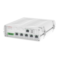
Figure 37: Features: Connect-OWS Mounting Options
DC Power Supply Wiring
The PoE input terminal block is a keyed Buchanan 796864-5 (or equiv.) connector. The
PoE supports dual floating power supplies to accommodate deployments with backup
power (e.g., A + B battery banks). All power inputs include overvoltage and reverse
polarity protection. The input voltage range is 10-30 VDC.
Table 23: Installation: Input Power Connector Pinout
Ground Lug
A #10 ground-lug is provided on the Connect-OWS chassis. Use this connection to
terminate a grounding wire. All Connect-OWS systems must be properly grounded.
 Loading...