CONNECT-OWS Installation Guidelines
70-00200-02-00 Proprietary Redline Communications © 2014 Page 7 of 70 December 3, 2014
Table 5: Features - CON Port LEDs .............................................................................. 17
Table 6: Features - Pinout for Data1 / Data 2 Port 232/485 ........................................... 18
Table 7: Features - DATA Port LEDs ............................................................................. 18
Table 8: Features - Pinout for ETH Ports ....................................................................... 19
Table 9: Features - ETH Port LEDs ............................................................................... 19
Table 10: Features - Pinout for PoE and ETH Ports ...................................................... 19
Table 11: Features - ETH Port LEDs ............................................................................. 19
Table 12: Features - Input Power Connector Pinout ...................................................... 20
Table 13: Features: Ethernet Port RJ-45 Pinout (T568B) .............................................. 23
Table 14: Site Survey - General Information Settings .................................................... 26
Table 15: Site Survey - Network & Syslog Server Settings ............................................ 26
Table 16: Site Survey - Serial Gateway Settings ........................................................... 27
Table 17: Site Survey - Serial Gateway Settings ........................................................... 27
Table 18: Site Survey - Radio Management Settings ..................................................... 28
Table 19: Site Survey - Path Profile Data ...................................................................... 28
Table 20: Site Survey: Operating Temperature Range .................................................. 33
Table 21: Site Survey: Power Requirements ................................................................. 36
Table 22: Installation: Installer Supplied Materials ......................................................... 40
Table 23: Installation: Input Power Connector Pinout .................................................... 49
Table 24: Installation: Installer Supplied Materials ......................................................... 53
Table 25: Configuration: Network and Wireless Settings ............................................... 61
Table 26: Installation: Installer Supplied Materials ......................................................... 61
Table 27: Configuration: Network and Wireless Settings ............................................... 63
LIST OF FIGURES
Figure 1: Notice - WEEE Logo ....................................................................................... 13
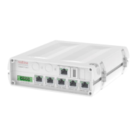
Figure 2: Features: Connect-OWS System .................................................................... 15
Figure 3: Features: Connect-OWS System Components ............................................... 16
Figure 4: Features: - Connect-OWS Features ............................................................... 17
Figure 5: Description - Connect-OWS DATA 1/2 and CON Port Pin Assignment ........... 18
Figure 6: Description - Connect-OWS ETH 1 and ETH 2 Port Pin Assignment .............. 18
Figure 7: Description - Connect-OWS ETH 1 and ETH 2 Port Pin Assignment .............. 19
Figure 8: Features: - Connect-OWS Dimensions ........................................................... 20
Figure 9: Features - Connect-OWS Power Terminal Block ............................................ 21
Figure 10: Features - Connect-OW (Integrated Antenna) Features ............................... 22
Figure 11: Features - Connect-OWS-ER (External Antenna) Ethernet Features ............ 22
Figure 12: Description - Connect-OWS PoE Port Pin Assignment ................................. 23
Figure 13: Features - Connect-OWS (integrated Antenna) Dimensions: 8 in ................. 24
Figure 14: Features - Connect-OWS-ER (External Antenna) Dimensions ..................... 24
Figure 15: Features - Connect-OW/Connet-OW-ER Ethernet Gland ............................. 24
Figure 16: Features - Ethernet Line Protection Device .................................................. 25
Figure 17: Features - Ethernet Line Protection Device Dimensions ............................... 25
Figure 18: Site Survey - RF Planning Fresnel Zone ....................................................... 28
Figure 19: Site Survey: Connect-OW Antenna Position ................................................. 29
Figure 20: Site Survey: Connect-OWS System Layout Options ..................................... 30
Figure 21: Site Survey: Connect-OWS Site Preparation ................................................ 31
Figure 22: Site Survey: Connect-OWS System Grounding ............................................ 32
 Loading...