Variomat 1 — 06.07.2016 – Rev. B English —
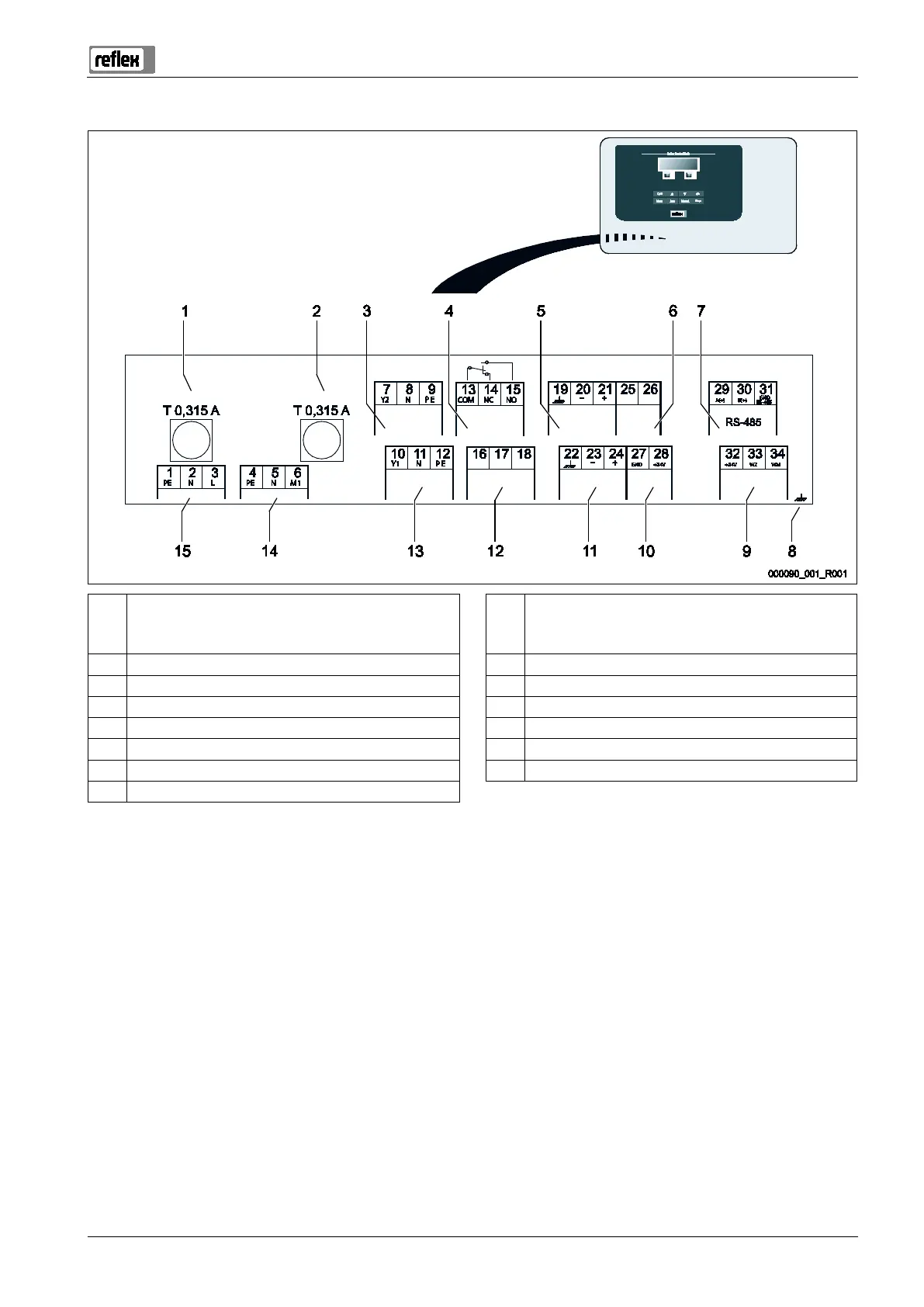
1 "L" fuse for electronics and solenoid valves 9 Digital inputs
• Water meter
• Insufficient water
2 "N" fuse for solenoid valves 10 Motor ball valve (energy connection)
3 Overflow valve (not for motor ball valve) 11 Pressure analogue input
4 Group message 12 External make-up request
5 Optional for second pressure value 13 Make-up valve
6 Motor ball valve (control connection) 14 "PU" pump
7 RS-485 interface 15 Mains supply
8 Shielding