4
Chapter 5
NOTE: Turn the ignition key to the right “OPERAT-
ING” position and then to the spring loaded “START”
position. At this point the key can be released and
the engine will crank until it starts. To stop the engine,
return the key to the “off ” position. On select engines
the stop position is straight up and down; others the stop
function is at a 180 degree position.
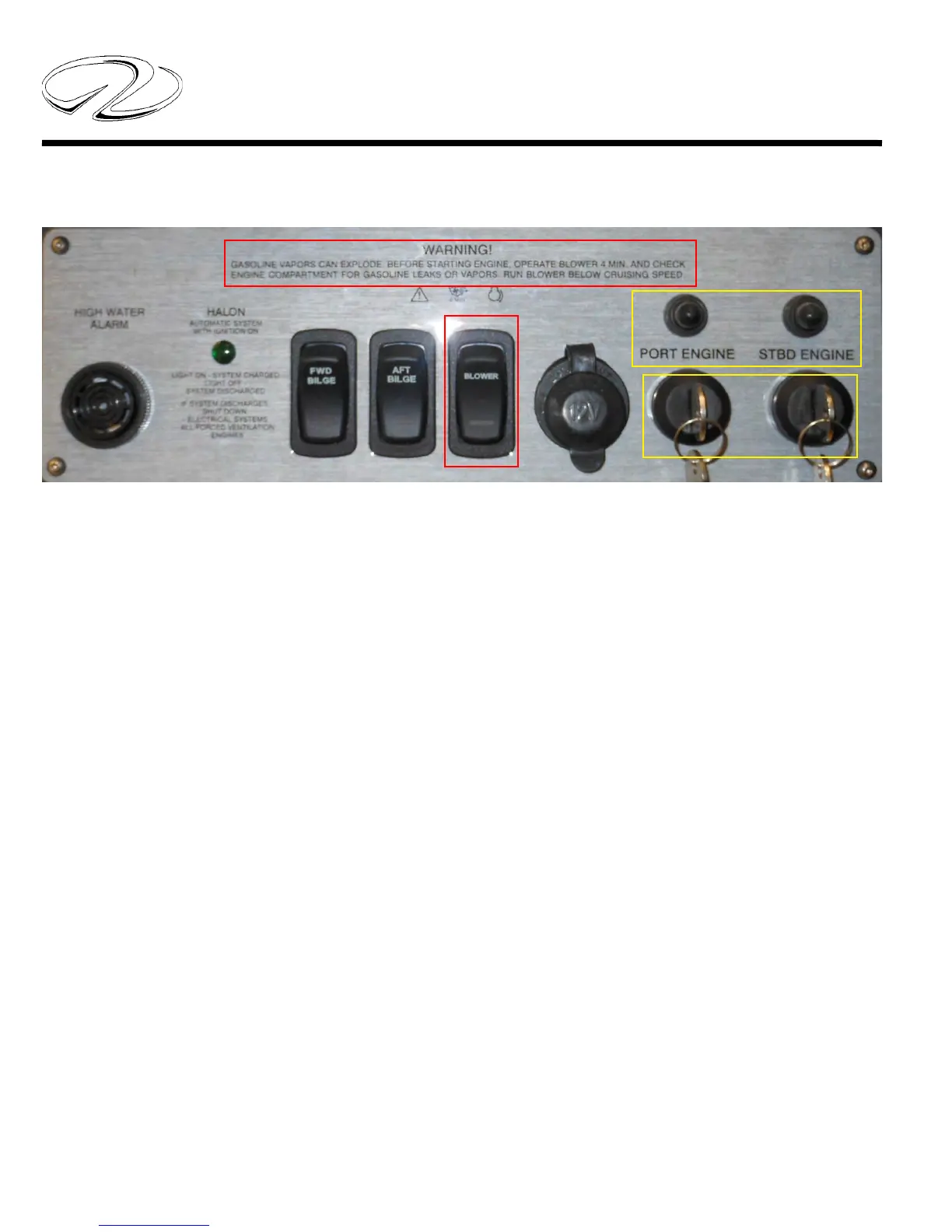
IGNITION SWITCH PANEL
Ignition key switches normally feature the following posi-
tions to identify key operating areas.
S= Stop
I= Operating Position (Ignition On)
II-III=Start (Spring Loaded)
Notice the areas above outlined in red as they refer to
important safety information. Read and understand the
blower information before attempting to start the engines.
The blower switch above is used on all gasoline engines.
Before turning on the blower switch do a snife test by
opening the engine hatch. At the same time check fuel
tank components. When assured the bilge is clear of any
fumes turn on the blower switch for at least 4 minutes
before attempting to start the engines. This will vacate
any gasoline fumes that are in the engine room (bilge or
sump). Continue to run the powered blower system below
cruising speeds after starting the engines.
Diesel engines on the other hand relay on natural ventila-
tion as the soul ingredient to develop engine horsepower
and to purge the bilge area.
The areas in yellow represent 20 amp ignition system break-
ers. There is one breaker per key switch. These breakers
protect the ignition switch circuitry. Should a breker “pop”
fi nd the cause of the malfunction before attempting to
restart the engine.