21
Systems
REMOTE BATTERY SWITCH OPERATION
Under normal conditions with the vessel charging sys-
tem working properly each remote battery switch should
show a lighted LED on the faceplate. When the remote
battery switch is in the “LOCK/OFF” position the LED
is not lighted.
IF THE REMOTE BATTERY SWITCH IS
TURNED TO THE “OFF” POSITION
THE ENGINE WILL NOT CRANK.
TURN THE REMOTE BATTERY SWITCH TO
THE “ON” POSITION
FOR THE ENGINE TO CRANK.
NEVER TURN THE REMOTE BATTERY
SWITCH OFF
WHEN THE ENGINE IS RUNNING!
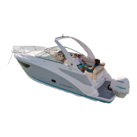
TYPICAL REMOTE BATTERY SWITCH
As part of the battery management system remote battery
switches are located in the engine room.
A remote battery switch is wired between each engine
and the “on-off ” universal battery switches located at the
battery management system panel. See the illustration.
Their purpose is to break up the long battery cable runs
from the batteries to the management center panel. Also,
they offer a shorter run from the battery to the starter
motor. In addition, the remote battery switch from the
bilge (sump) provides an avenue to shut down the battery
system during engine or sump routine maintenance
functions. Remote battery circuits feature 120 volt breaker
protection.
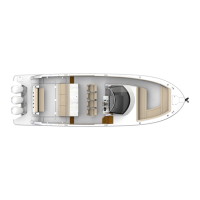
If the remote battery system fails the skipper can energize
the remote battery switch manually through the magnetic
latch which is located on top of the manual overide switch.
Presently the latch features a yellow color. The energized
latch permits power for engine starting.
Each remote battery switch provides a continuous rating
of 300 amps DC and a cranking rating of 1250 amps DC.
Normally remote battery switches are “in line” between
each battery and the engine they serve.
TYPICAL
REMOTE
BATTERY
SWITCH
TYPICAL
BREAKER
MAGNETIC
LATCH
MANUAL
OVERIDE
SWITCH
1. Normal operation of the remote battery switch is
completely to the left in the auto or “remote” position.
Notice latch position is up (disengaged).
MAGNETIC
LATCH
UP
LEFT OR
REMOTE
POSITION