19A-61
COOLING
Plenum chamber: Removal - Refitting
K4M
19A
REMOVAL
I - REMOVAL PREPARATION OPERATION
a Position the vehicle on a two-post lift (see Vehicle:
Towing and lifting) (02A, Lifting equipment).
a Remove:
- the engine cover,
- the front wheels (see Vehicle: Towing and lifting)
(35A, Wheels and tyres),
- the front section of the front wheel arch liners (see
Front wheel arch liner: Removal - Refitting)
(55A, Exterior protection),
- the engine undertray bolts,
- the engine undertray,
- the front bumper (see Front bumper: Removal -
Refitting) (55A, Exterior protection).
a Drain the cooling system (see Cooling circuit Drai-
ning) .
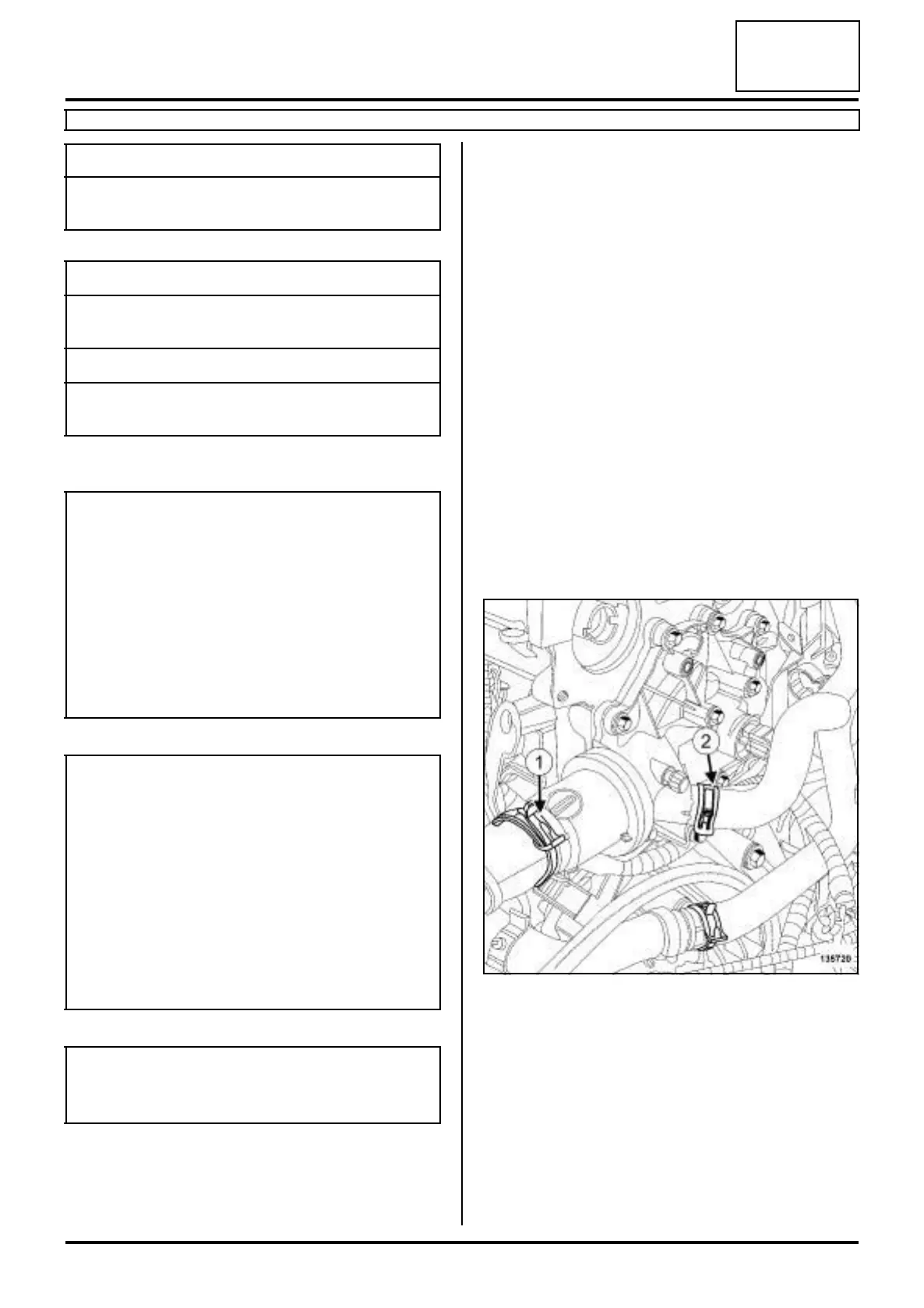
a Remove using the (Mot. 1448) :
- the top hose clip (1) from the coolant outlet unit,
- the heater matrix hose clip (2) .
a Disconnect:
- the top hose on the coolant outlet unit,
- the heater matrix hose.
a Remove the coolant temperature sensor (see 19A,
Cooling, Coolant temperature sensor: Removal -
Refitting, page 19A-101) .
Essential special tooling
Mot. 1448 Long nose pliers for hose
clips.
Tightening torquesm
coolant outlet unit bolts
(initial torque)
4 N.m
coolant outlet unit bolts 12 N.m
heater matrix hose retai-
ning bracket
10 N.m
IMPORTANT
When working in the engine compartment, take
care as the radiator fan(s) may start up unexpecte-
dly (risk of being cut).
To avoid any risk of serious burns when the engine
is hot:
- do not open the expansion bottle cap,
- do not drain the cooling system,
- do not open the bleed screw(s).
WARNING
When carrying out a repair that requires a complete
change, it is essential to flush the circuit with clean
water, blast compressed air through the circuit to
drive out the water, fill and bleed the circuit and
then measure the effective protection.
The criteria to be met are:
-protection down to -25˚C ±±
±±
2 for cold and tempe-
rate countries,
- protection down to -40˚C ±±
±±
2 for "extreme cold"
countries.
WARNING
Prepare for the flow of fluid, and protect the sur-
rounding components.
135720