Renesas RA Family Getting Started with Low Power Applications for RA6 and
RA4 Groups
R11AN0471EU0104 Rev.1.04 Page 21 of 40
Oct.1.21
Power On
Reset
CPU : Clo ck Source
HOCO
Clock Sources
Low Power Mode
(A)
(B)
(C)
(D)
(b)
CPU : Clo ck Source
MOSC
CPU : Clo ck Source
MOCO
CPU : Clo ck Source
LOCO
CPU : Clo ck Source
SOSC
(E)
CPU:
Subsystem clock
operation
CPU:
Subsystem clock
operation
Snooze Mode
Sleep Mode
(F)
Normal Mode
(1)
(2)
(6)
(c)
(d)
(e)
(5b) (5a)
Deep Software
Standby Mode
CPU : Clo ck Source
MOCO
(a)
CPU : Clo ck Source
SOSC
Software Standby
Mode
(7)
N
o
r
m
a
l
M
o
d
e
(3)
(4)
Normal Mode
Normal Mode
Normal Mode
Normal Mode
Clock Change Mode -
Transition
Low Power Mode - Transition
Internal Reset State
(8a)
(8b)
Internal Reset State
(LP) – Long Press Event
(SP) – Short Press Event
(RTC)
– RTC Event
(Timer)
– Timer Event
(LP)
(LP)
(LP)
(LP)
(LP)
(LP)
(LP)
(LP)
(LP)
(LP)
(SP)
(SP)
(SP)
(SP)
(SP)
(SP)
(LP)
/(SP)
(SP)
(RTC)
(RTC)
(Timer)
(Timer)
(LP)
/(SP)
(f)
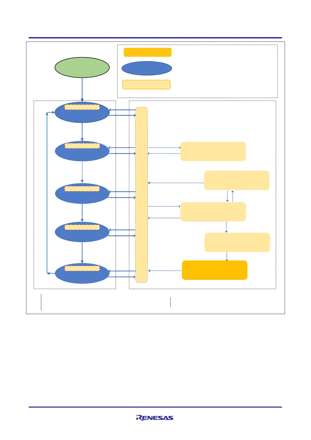
Figure 18. Clock Changing and LPM Transition
In the above Figure 18, the blue colored oval shaped blocks (B) though (F) represent the different clock
states used in the application, and (b) through (f) labeled arrows are different transition path it takes when
changing the clock.
The yellow blocks are the different LPM states as applicable to the MCU, and the (1) through (8) numbered
arrows, represents the transition path at the different Low Power Modes.
Note: The dotted block represents the Clock Change Mode transition on the left and LPM Transition on the
right as shown in Figure 18.
Note: The Deep Software Standby Mode and Snooze Mode is entered via Software Standby mode. For the
Snooze and Deep Software Standby mode, from the application perspective the MCU and LPM
drivers handles the Software Standby mode internally, while it is configured for the Snooze or Deep
Software Standby Mode.

 Loading...


