Renesas Starter Kit+ for RZ/T2M 6. Configuration
R20UT4939EG0100 Rev. 1.00 Page 50 of 87
Apr 20, 2022
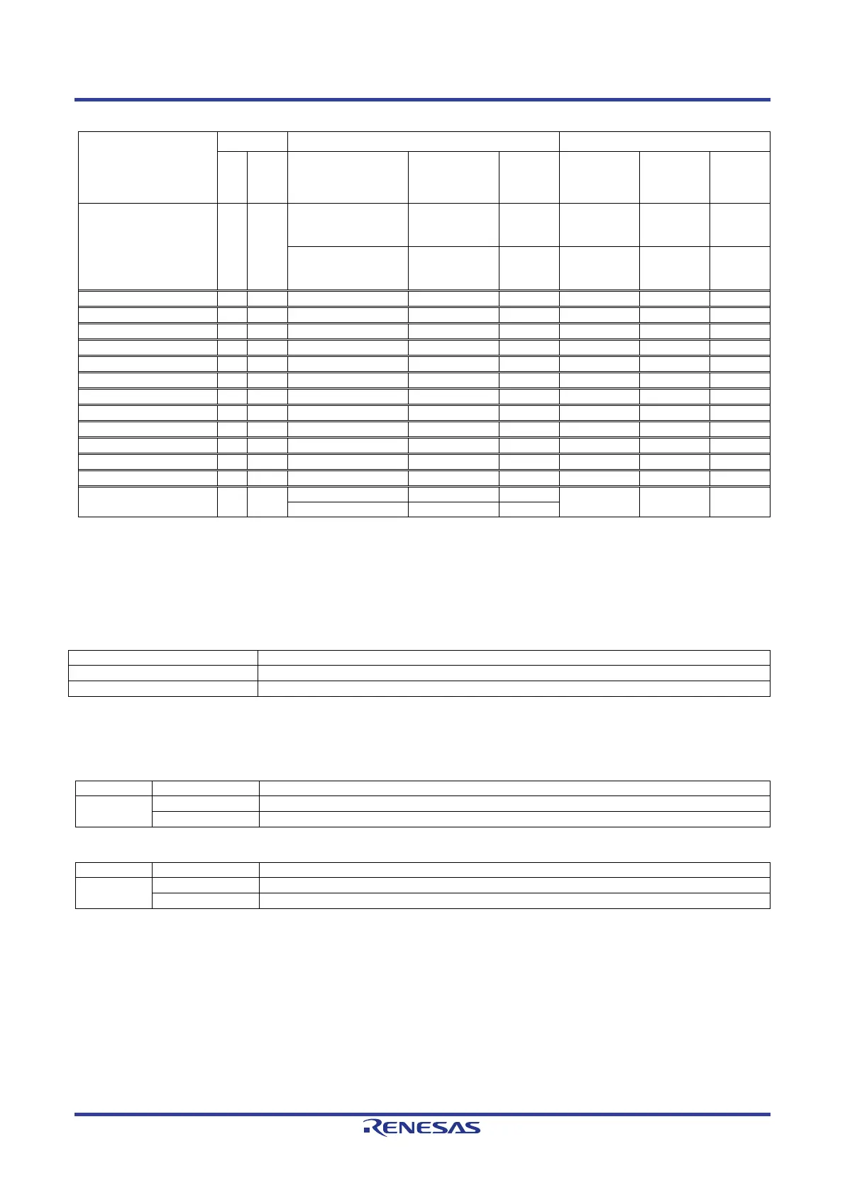
Table 6-33: Ethernet Configuration Option Links (3)
Signal name
Pin
Port
Signal Fit DNF
Interface
/Function
Fit DNF
ETH2_TXCLK D3 P00_6
ETH2_TXCLK
CN23
- IC16.37 - -
CS5#
CN23
- JA3-A.27 - R296
ETH2_REFCLK_25 - -
IC16.63 R265 -
*
1
: In the default RSK+ configuration, ETH2_REFCLK_G signal is not connected to the XTAL1 pin of the
Ethernet controller IC (IC16). If you want to connect the external clock (X1) on the RSK+ to the Ethernet
controller IC, configure as shown in Table 6-33 above.
Table 6-34 below details the function of the switches associated with the Ethernet.
Table 6-34: Ethernet Configuration Switch Settings
Enable the external bus signal and Ethernet. *
1
Enables signals other than the external bus. (CAN, Emulator, I
2
C, etc.)
*
1
: BUS (SDRAM) and Ethernet port 2 cannot be used at the same time.
Table 6-35 and Table 6-36 below details the function of the jumpers associated with the Ethernet.
Table 6-35: Ethernet Configuration Jumper Settings (1)
CN17
Connect 3.3V Power rail to VCC1833_2. (When using SDRAM)
Connect 1.8V Power rail to VCC1833_2. (When using Ethernet port 2)
Table 6-36: Ethernet Configuration Jumper Settings (2)
When using 3 ports in the same PHY mode
When ports 0 and 1 use the same PHY mode and port 2 uses different PHY modes
*
: When using VCC1833_2 at 3.3 V, use a jumper setting of 2-3.
 Loading...


