Renesas Starter Kit+ for RZ/T2M 6. Configuration
R20UT4939EG0100 Rev. 1.00 Page 60 of 87
Apr 20, 2022
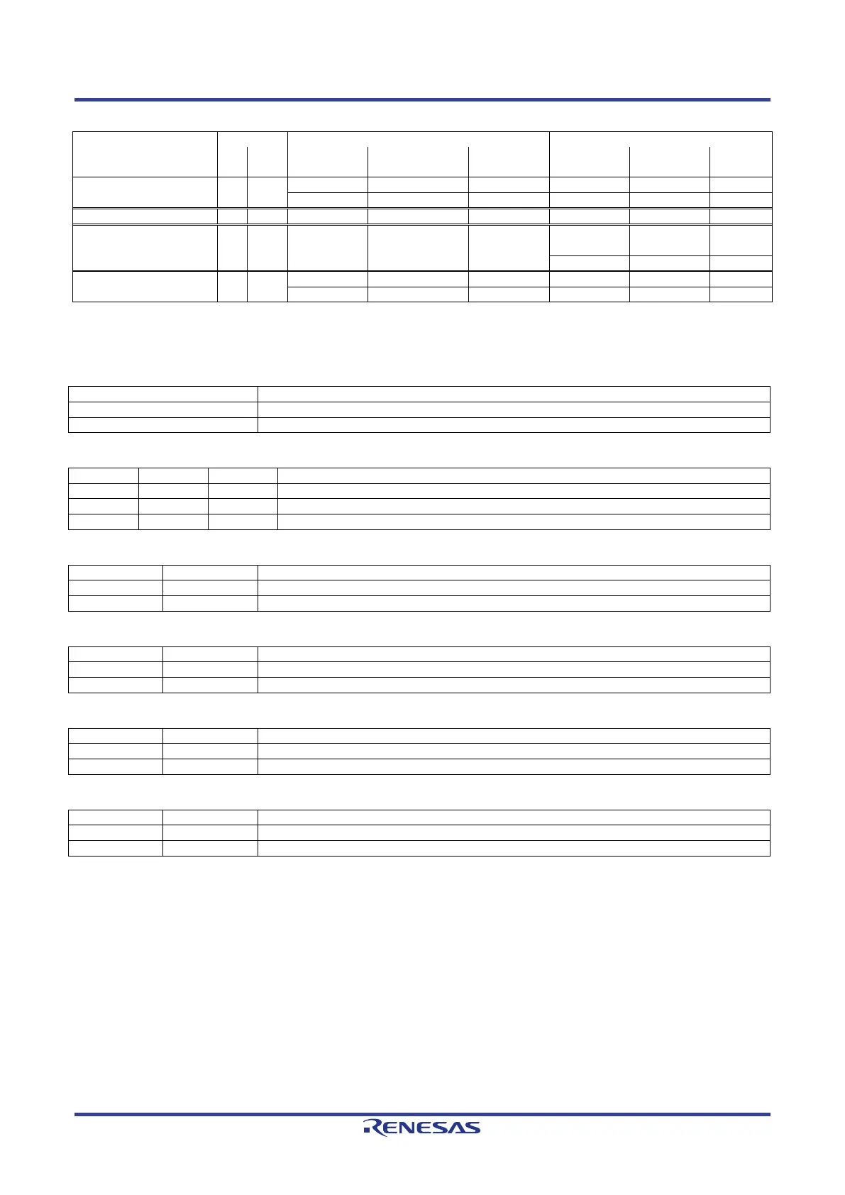
Table 6-51: MTU & POE & Timer Configuration Option Links (2)
Signal name
Pin
Port
Signal Fit DNF
Fit DNF
RLED1_M2_VP C20 P19_4
ETH_LED4 G15 P19_7 ETH_LED4
- -
ETH_LED4.A
-
RLED2_M2_WN B20 P20_0
Table 6-52, Table 6-53, Table 6-54, Table 6-55, Table 6-56, Table 6-57 below details the function of the
switches associated with the MTU & POE & Timer.
Table 6-52: MTU & POE & Timer Configuration Switch Settings (1)
Enable the external bus signal.
Enables signals other than the external bus. (CAN, Emulator, I
2
C, etc.)
Table 6-53: MTU & POE & Timer Configuration Switch Settings (2)
Enable the "M1_VP" signal.
Enable the "RS485_RXD" signal.
Enable the "SCI_RXD" signal.
Table 6-54: MTU & POE & Timer Configuration Switch Settings (3)
Enable the "M1_UN" signal.
Enable the "SCI_RTS" signal.
Table 6-55: MTU & POE & Timer Configuration Switch Settings (4)
Enable the "MB_RST#" signal.
Enable the "M1_WN" signal.
Table 6-56: MTU & POE & Timer Configuration Switch Settings (5)
Enable the "SCI_TXD" signal.
Enable the "M1_VN" signal.
Table 6-57: MTU & POE & Timer Configuration Switch Settings (6)
Enable the "M2_POE" signal.
Enable the "TRACE_CTL" signal.
 Loading...


