Only qualified persons
should change settings
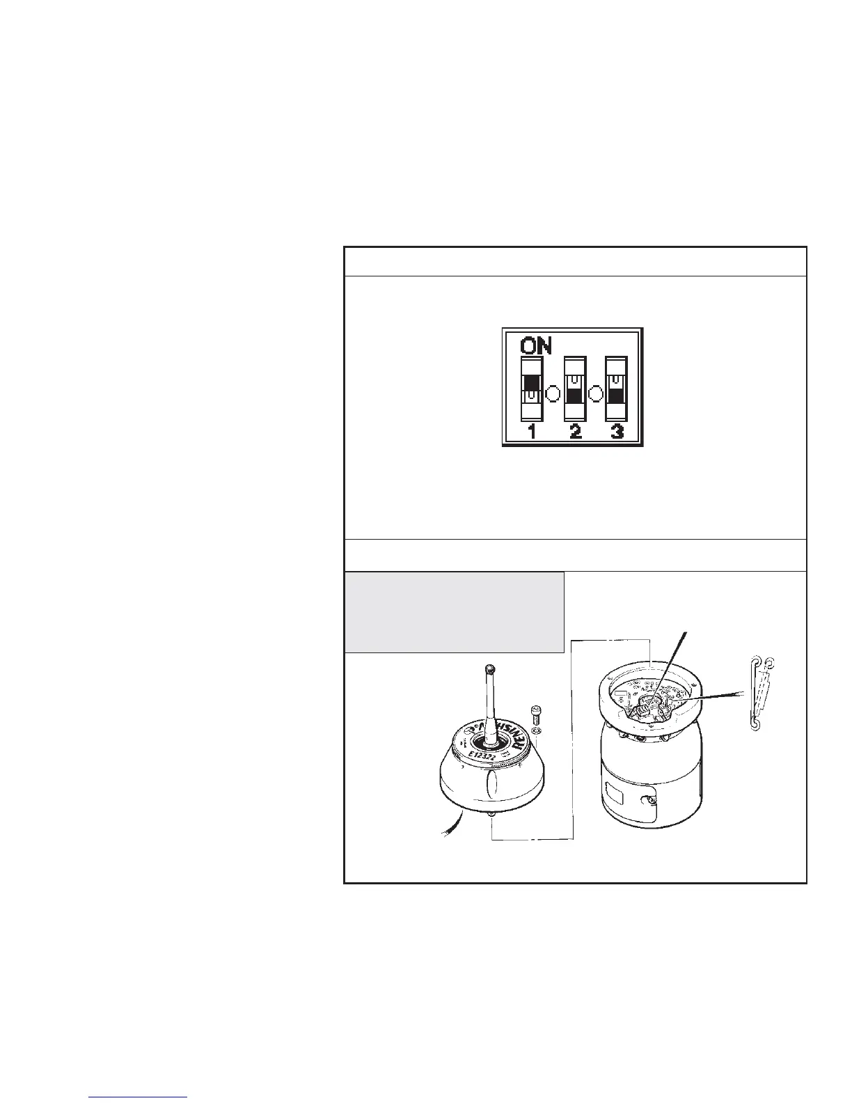
Remove the probe head to gain
access to the switches and sockets.
OPTIONS SETTING SWITCH
System settings are shown
opposite.
ENHANCED TRIGGER CIRCUIT
Probes subjected to high levels of
vibration or shock loads, may
release spurious readings. The
enhanced trigger circuit improves
the probes resistance to these
effects.
When the circuit is enabled, a
constant nominal 7 millisecond
delay is introduced to the probe
output.
It may be necessary to revise
program software to allow for the
increased stylus overtravel.
To activate the enhanced trigger
circuit, the wire link is transferred
manually :
From SKT 1-2 (factory set)
To SKT 3-2 (enabled)
TAKE CARE
KEEP ALL COMPONENTS CLEAN -
DO NOT ALLOW COOLANT OR
PARTICLES TO ENTER THE PROBE.
DO NOT TOUCH ELECTRONIC
COMPONENTS WHEN CHANGING
SWITCH SETTINGS.
MODE
Optical on
Optical off
(factory set)
A-2033-1115/1116
MODE
Optical on
Time out
(factory set)
A-2033-1099/1100
TIME-OUT
134 seconds
(factory set)
TIME-OUT
33 seconds
DEBOUNCE
5 seconds
(factory set)
12
3
OPTIONS SETTING SWITCH
DEBOUNCE
9 seconds
2 3
1
OPTIONS SWITCH
ENHANCED TRIGGER CIRCUIT
Align head - OMP contacts
before fitting head onto OMP
Do not rotate head when
located in OMP housing
Grease 'O' ring
before refitting head
1-12
OPTIONS SETTING SWITCH AND ENHANCED TRIGGER CIRCUIT
see page 1-42
SOCKET (SKT) 1-2
SOCKET (SKT) 2-3
ENHANCED
CIRCUIT
2
13