A workpiece set-up and inspection probe is in effect another
tool in the system. A probe cycle may be included at any
stage of the machining process.
Signals are transmitted between the probe and the machine
control, via the OMP and OMM + MI 12 or alternatively the
OMP and OMI.
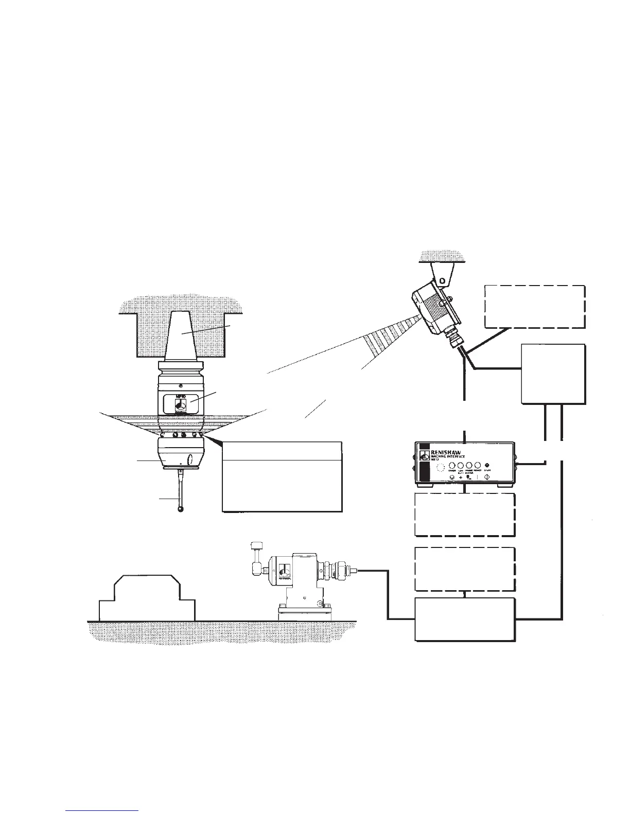
TYPICAL PROBE SYSTEMS
1-2
Workpiece
Probe head
Stylus
Machine spindle
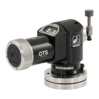
Typical tool
setting probe
CNC
machine
control
Cable
Battery cover
Shank (size 25 - 50)
Optional - PSU3
power supply unit
Optional - PSU3
power supply unit
OMP - LEDs
Mounting bracket
OMI (one only)
+ CNC control
Optional - PSU3
power supply unit
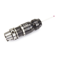
MP10
inspection
probe
3 x Receive diodes
6 x Transmit LEDs
1 x Probe status LED
MI 12 interface unit
or MI 12 board
OMM (one or two)
+ MI 12
+ CNC control
MI 5, MI 8 or
MI 8-4
interface
unit
SEE PAGES 1-38, 1-39 & 1-40
OMM - Optical module machine
OMP - Optical module probe
OMI - Optical machine interface