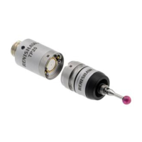
OMP40-2 installation guide
3.2
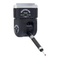
System
installation
OMM-2 / OMI-2T / OMI-2H / OMI-2 /
OMI / OMM positioning
To assist in finding the optimum position for the
OMM-2 / OMI-2T / OMI-2H / OMI-2, the signal
condition is displayed on a multi-coloured LED.
To assist in finding the optimum position for the
OMI, the signal strength is displayed on an OMI
multi-coloured LED.
To assist in finding the optimum position of the
OMM during system installation, signal strength
outputs are available on the MI 12 interface.
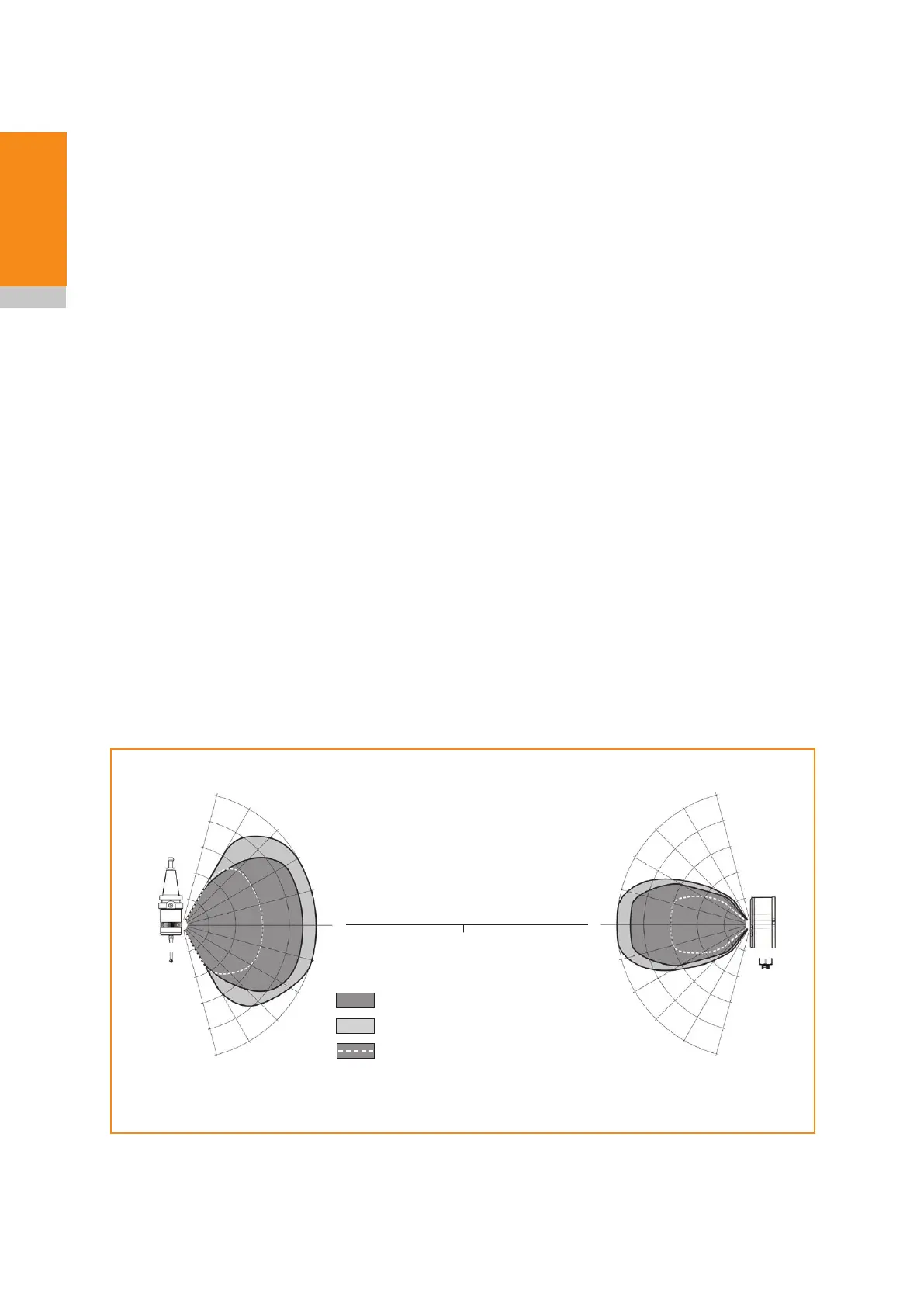
Performance envelope with an
OMM-2 / OMI-2T / OMI-2H / OMI-2
(modulated transmission)
The probe and OMM-2 / OMI-2T / OMI-2H /
OMI-2 diodes must be in each other’s field of view
and within the performance envelope shown. The
OMP40-2 performance envelope is based on the
OMM-2 / OMI-2T / OMI-2H / OMI-2 being at 0°
and vice versa.
OMP40-2
OMM-2
OMI-2T
OMI-2H
OMI-2
0°
Optical
centre line
60°
45°
45°
15°
30°
30°
15°
60°
0°
60°
45°
45°
15°
30°
30°
15°
60°
75°
4 (13.1)
3 (9.8)
2 (6.5)
1 (3.3)
5 (16.4)
4 (13.1)
3 (9.8)
2 (6.5)
1 (3.3)
5 (16.4)
75°
75°
75°
Switch-on / switch-off
Operating – standard power mode
Operating – low power mode
Typical plot at 20 °C (68 °F) 360° transmission around probe axis in m (ft)
 Loading...