5.8 Inserting the filter unit and collecting receptacle
The filter unit serves as an air outlet for the air flow generated by the comminuting rotors.
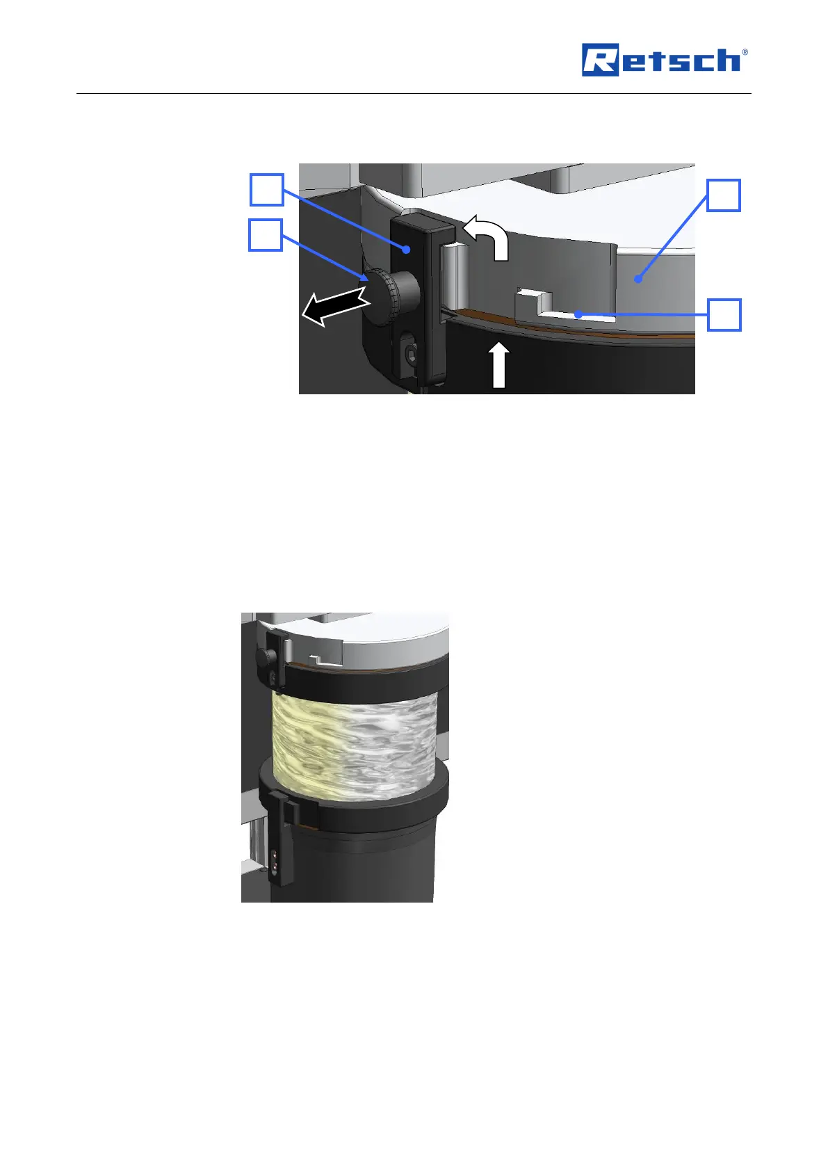
Fig. 16: Mounting and removing the filter unit
• As shown in the illustration, insert the bayonet fixing(BV) that is on the filter
unit (J) into the discharge flange(AV).
• Turn the filter unit in a clockwise direction in order to engage the bayonet
fixing.
• To remove the filter unit, pull the detent pin (RB) to release the bayonet
fixing (BV).
Alternatively, the collecting receptacle can be put onto the discharge flange directly. In the
latching position (BV) the air flowis prevented from escaping.
In the latching position (LS) a gap remains between the discharge flange and the collecting
receptacle remains and this allows air to flow out .
Fig. 17: Collecting receptacle and filter unit
5.9 Starting the grinding process
Switch on the power switches on the back of the device.
Press the START button.
NOTE
Make sure the device is running before you fill in the sample material. Otherwise, motor
blockages can occur as the device is starting up.