13Bosch Rexroth AG
4. Accessori
F A richiesta possono essere montati
presso la Bosch Rexroth AG i seguenti
componenti pronti per l’uso. È altrettanto
possibile procedere in qualsiasi momento
ad un montaggio successivo.
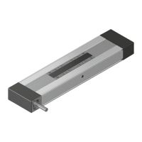
4.1 Sistema con sensore
magnetico
(tutte le grandezze)
1 Presa con spina
2 Sensore magnetico
2a sensore magnetico con spina
3 Canalina di fissaggio
4.2 Sistema interruttori con
interruttori meccanici ovvero
induttivi
(solo CKR 25-200 con
uso della piastra di
accoppiamento)
4 Interruttore meccanico
5 Interruttore induttivo
6 Piastra di accoppiamento
F I due sistemi interruttori non posso-
no essere montati insieme su un lato!
4.3 Azionamento
7 Motore
8 Riduttore
9 Flangia
4. Accessoires
F Sur demande, les composants sui-
vants peuvent être montés en usine chez
Bosch Rexroth AG. Un rééquipement est
possible à tout moment.
4.1 Système de commutation et
capteur de champ magnétique
(toutes tailles)
1 Prise et fiche
2 Capteur de champ magnétique
2a Capteur de champ magnétique
et fiche
3 Chemin de câbles
4.2 Système de commutation
avec interrupteurs mécani-
ques ou inductifs
(avec une plaque de liaison
uniquement pour le
CKR 25-200)
4 Interrupteur mécanique
5 Interrupteur inductif
6 Plaque de liaison
F Les deux systèmes de commu-
tation ne peuvent pas être montés
ensemble sur un seul côté !
4.3 Entraînement
7 Moteur
8 Lanterne
9 Accouplement
4. Attachments
F If desired, the following compo-
nents can be premounted by Bosch
Rexroth AG, ready for use by the cus-
tomer. They can also be retrofitted at any
time.
4.1 Switching system with
magnetic field sensors
(all sizes)
1 Socket and plug
2 Magnetic field sensor
2a Magnetic field sensor with plug
3 Mounting duct
4.2 Switching system with
mechanical or proximity
switches
(only for CKR 25-200 when
using a connecting plate)
4 Mechanical switch
5 Proximity switch
6 Connecting plate
F The two switching systems cannot
be mounted together on one side!
4.3 Drive
7 Motor
8 Timing belt side drive
9 Motor mount
Instructions CKRR320103679 (2009.09)
 Loading...