6
User manual RF-KIT Power Amplifier RF2K-S
3.2 Control elements and connections
1 Power switch O n / O ( 1 ) (main switch)
This rocker switch switches the device on / o .
2 Touch screen - GUI
This Touch screen controls the device in all operating states.
Also you receive context-related information about the operating
status of the device.
3 ANT 4
50 Ω antenna socket SO-239 (PL-259)
4 ANT 3
50 Ω antenna socket SO-239 (PL-259)
5 ANT 2
50 Ω antenna socket SO-239 (PL-259)
6 ANT 1
50 Ω antenna socket SO-239 (PL-259)
When device is switched o , TRX (17) is looped through to
ANT 1 (6) .
7 PTT
RCA connector for transmit/receive switching
At the center contact (+) of the connector PTT (7) +5 V is pre-
sent.
8 Power On External
RCA connector for remote control: The device can be switched on re-
motely by applying + 12V DC (at least 10 V, max 15 V!) to the center
contact. The power switch O n / O ( 1 ) must be switched o (“0“).
When DC voltage drops, the PA switches o .
9 Power jack
A plug for this power socket is included and can be wired to the user
supplied power cord capable of 16 Amps, that meets their countries
power plug requirement.
10 Fuse - automatic circuit breaker 16 A
If this automatic circuit breaker trips several times in succession a
serious fault condition may exist!
WARNING!
Do not open the device by yourself, contact the manu-
facturer!
11 Ground connector
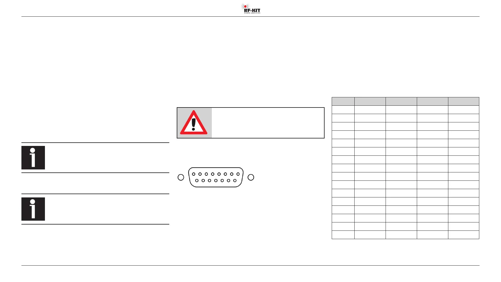
12 Multifunction connector DB-15
1
9
8
15
(Plugview)
DB-15 External Antenna Select Input (Pin 1-4):
The RF2K-S internal controller can store tuner settings for up to 16 antennas
per band. Your external antenna selectors connect via the Ant 1 connector.
With this arrangement the amplifier must be made aware which of the up
to 16 antennas is in use. This is done by providing BCD data toPins 1-4 as
detailed in the table. Antennas may be mono or multi-band.
1 - In A BCD
input from ext antenna selector system.*
2 - In B BCD
input from ext antenna selector system.*
3 - In C BCD
input from ext antenna selector system.*
4 - In D BCD
input from ext antenna selector system.*
* Max. voltage: 15 V for RF2K-S V1 / 50 V for RF2K-S V2.
For the version number, see the nameplate at the back of the PA.
Addressing externally connected and managed antennas
( 1 = active; 0 = inactive):
Antenna Pin 1 (In A) Pin 2 (In B) Pin 3 (In C) Pin 4 (In D)
1
0 0 0 0
2
1 0 0 0
3
0 1 0 0
4
1 1 0 0
5
0 0 1 0
6
1 0 1 0
7
0 1 1 0
8
1 1 1 0
9
0 0 0 1
10
1 0 0 1
11
0 1 0 1
12
1 1 0 1
13
0 0 1 1
14
1 0 1 1
15
0 1 1 1
16
1 1 1 1