27
User manual RF-KIT Power Amplifier RF2K-S
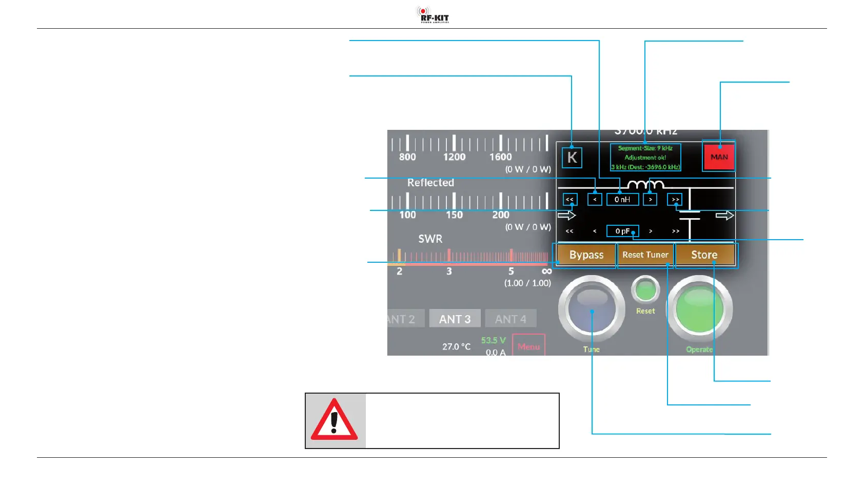
6. Antenna tuner
6.1. Description
The internal antenna tuner comprises an LC circuit configured as an L
Match. This matches the impedance of the amplifier‘s RF pallet output to
the selected antenna connector.
The circuit may be configured with leading L or leading C as required, by
touching switching area K.
Available values of C: Minimal 0.0 pF; Max. 1275 pF
Available values of L: Minimal 0.0 μH; Max. 10,16 μH
A match may be found “at the push of a button“ (tuner mode “MAN“). In
this case, after touching the switching areaTune, the Tuner will automati
-
cally determine the required configuration and settings.
You may alternatively perform the tuning process manually by touching
switching area <</< or >/>> (tuner mode “MAN“) or refine a configuration
that has already been determined.
Regardless how a setting has been determined, by touching switching
area Store the associated values by antenna and band frequency segment
can be stored for later retrieval (tuner mode “AUTO“). Further tuning will
not be required unless the connected antenna/feeder characteristics have
changed since a tune operation was last performed.
A database is created for each antenna connection, in which settings alrea
-
dy determined for this antenna are stored.
Connected antennas may be mono-band or multi-band. In the latter case
settings data may be stored for each band and frequency segment on
which the antenna will be used.
Switching area Tune
Pressing this switching area triggers a tuning process of the antenna
Switching area Store
Switching area Reset Tuner
NOTE:
If the antenna tuner is activated, but no valid
tuning data is stored yet for the used frequency,
transmitting is not possible!
Indication area Segment-Size
Switching area/
Indication area
Tuner-Mode
Selection
“AUTO“ (green) /
“MAN“ (red)
Indication area
C (in pF)
Switching area >>
Increase value coarse
Switching area >
Increase value ne
Indication area L
(in μH)
Switching area K
Selection conguration antenna tuner
Switching area <<
Decrease value coarse
Switching area <
Decrease value ne
Switching area Bypass
Selection “Pass“ / “Bypass“