9
User manual RF-KIT Power Amplifier RF2K-S
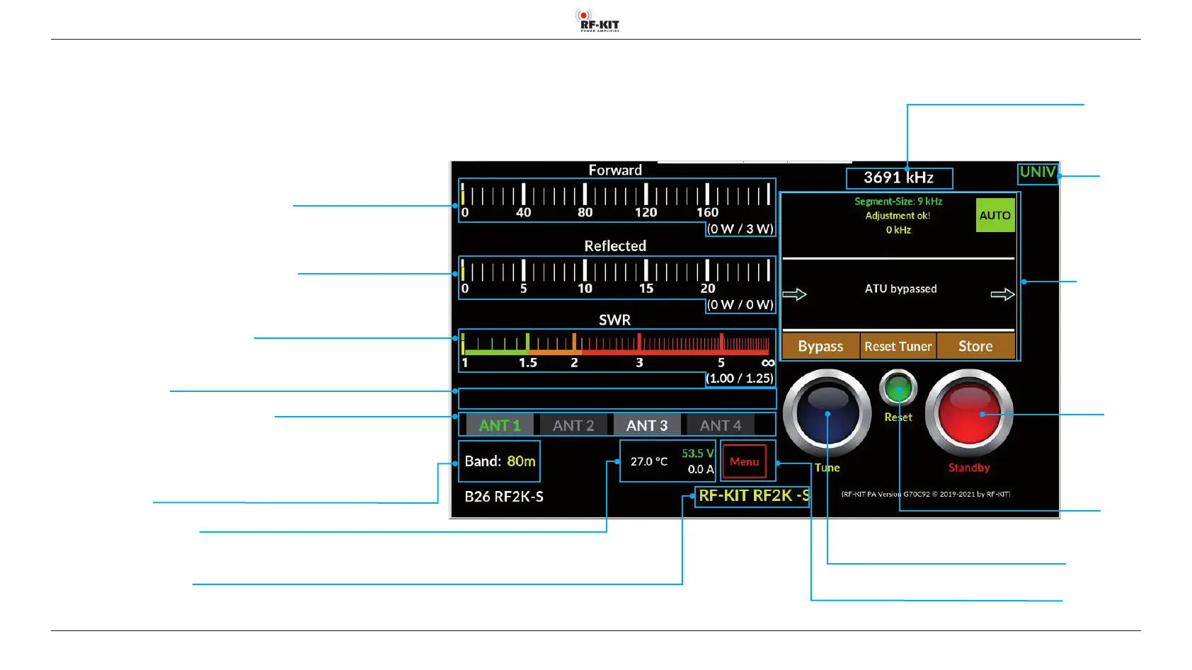
Indication area Forward Power (analog PEP and digital / maximal)
Indication area Reected Power (analog PEP and digital / maximal)
Indication area SWR (analog PEP and digital / maximal)
Indication area Error Messages
Switching area/Indication area Currently Selected Antenna
Individual connections for a band are assigned in the „Antennas“ user menu.
Antenna(connections) available for the selected band are displayed with white labeling.
The antenna currently connected to the device is displayed with green label.
Dark grayed out buttons cannot be selected.
Indication area Used Band
Switching area
Interface
Switching area/
Indication area
Antenna Tuner
Indication area Operating Parameters
(Temperature output stage, end transistor supply voltage, output stage current consumption)
Indication area Personalization Text
An individualization text to be edited in the user menu (e.g. call sign) is displayed here
Indication area
Frequency TRX
Switching area
Standby
Switching between
“Standby“ (red)
“Operate“ (green)
5. Using the device locally
5.1 Turning device on
► Turn on the device using power switch On/O (1).
The Touch screen (2) lights up and shows the user interface:
Switching area Menu
Touching this switching area activates the user menu
Switching area Tune
Touching this switching area triggers a tuning process
Switching area
Reset PA
If the PA switches o due to an error, it is reactivated after actuating this switching
area; the error message (e.g. “zu hohes SWR“ vanishes)