Calibration
CGS-240 Manual 6/15/2021
Page 44 of 148
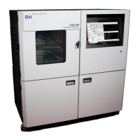
14) After saving, observe the corresponding
coefficients window to verify your coefficients
were properly saved:
Depending on which probe was calibrated,
select either [Pl] Low Pressure Coefficients, or
[Ph] High Pressure Coefficients, from the drop-
down menu.
Ensure that the displayed coefficients reflect
those saved in the previous step.
Repeat steps 4 through 14 for the other pressure sensor.
5.1.3 PRESSURE SENSOR REINSTALLATION
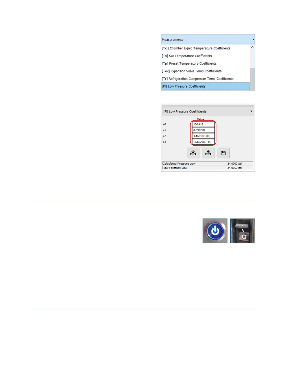
1) Power down the CGS-240:
a. Press the front panel power button and wait for the unit to
complete shutdown.
b. Switch the main power Off.
If you removed the AN-7/16-20 adapter, use a new copper sealing gasket between the transducer
and the AN side of the fitting. Each sensor has either an O-ring or a bonded washer to seal it at the
manifold.
If the O-ring or bonded washer are worn/damaged, replace them when reinstalling the transducer
to the manifold. Note that P
H
is installed to the left, and P
L
is installed to the right. The green circular
connectors are universal and are not associated to either sensor, so it does not matter which
connector goes to which sensor.
5.1.4 ALTERNATIVE PRESSURE CALIBRATION PROCEDURE: INDEPENDENT SENSOR CALIBRATION
This procedure assumes the sensors are calibrated independently of the CGS-240
Refer to section 5.1.1 for instructions on pressure sensor removal.
 Loading...