24
Section I :: User
The Rhoss Multichiller Sequencer enables the management of hydrau-
lically parallel chillers in medium/large HVAC systems. The optimization
of operating times and the activation of the single units is controlled
by logics which reward energy efciency while guaranteeing long-term
reliability.
The allows:
The software, representing the heart of the system, has been designed
and tested within the Ross Research&Development structure and is
able to acquire and manage all the main variables of the connected
chillers. The sequencer also interfaces with the main BMS present on
the market, guaranteeing complete control of any type of system.
S.p.A. bases the development of its products on long-stan-
ding experience in the eld of HVAC, continued investment in techno-
logical product innovation, rigorous quality processes and procedures
with functional tests on 100% of its production and the most innovative
production technology available on the market. S.p.A. does
not guarantee, however, that all aspects of the product and softwa-
re included in the product will meet the needs of the nal application,
even though the product is manufactured according to state-of-the-art
techniques.
In medium/large HVAC systems, offers the possibility to ma-
nage several hydraulically parallel chillers thanks to the
The optimization of operating times and the activation of the single units
is controlled by logics which reward energy efciency while guarante-
eing long-term reliability. The system also interfaces with the main BMS
present on the market.
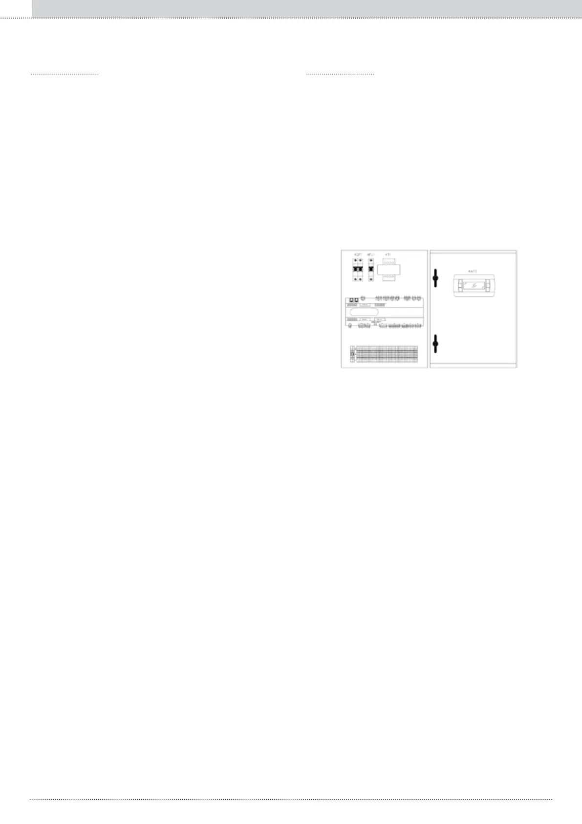
By means of an electrical panel (iPSA) of reduced dimensions (400
base x 600 height x 200 depth) to be installed in a dedicated tech-
nical location (normally in the heating and cooling plant), thermody-
namic management is possible (on/off of refrigerant units in reference
to a setpoint), and the monitoring of the system (chiller alarms, main
operating parameters of the refrigerant units, main parameters of the
system).
Regulation is proportional to machine saturation. The regulation of the
load takes place by stepping the machine rst, until it is off, while kee-
ping the others at 100% power, proceeding in the same manner until all
of the groups are deactivated. The system setpoint is regulated to the
value of the delivery temperature.
By means of the latter, it is possible to manage a number of centralized
functions of the system such as ON-OFF, the setting of operating mode
(summer/winter), a general system alarm, and the alarms for system
water ow and system pump thermal protection.
The units (the maximum number of units which can be connected is 10)
are connected to the sequencer by means of an RS485 serial network
(maximum length of network 1km) using a MASTER proprieta-
ry communications protocol.
• do not allow electronic circuits to come into contact with water. Rain,
humidity and all liquids or condensation contain corrosive minerals
which can damage electronic circuits. In all cases the product must
be used or stored in environments that comply with the temperature
and humidity levels specied in this manual;
• do not install the device in particularly hot environments. Tempera-
ture levels which are too high can reduce the lifespan of the elec-
tronic devices, damage them and deform or melt their plastic parts;
• do not attempt to open the device in ways not described in the ma-
nual;
• do not drop, knock or shake the devices as this may cause irrepara-
ble damage to their internal circuits and mechanisms;
• do not use corrosive chemicals, solvents or aggressive detergents
to clean the devices;
• do not use the product in applications other than those specied in
the manual.
◦ management of several hydraulically parallel chillers;
◦ display and modication of the summer/winter operating mode in
the heat pump units;
◦ display and modication of the system setpoint values;
◦ display of the water temperatures, pressures and the operating sta-
tus of the compressors;
◦ display of any alarms.
Each product, depending on its advanced technological level,
requires a certain level of programming and conguration allowing it to
operate at its best for the specic application. The lack of this study, as
indicated in the manual, can lead to malfunctioning in the nal products
for which S.p.A. declines all responsibility. Only qualied per-
sonnel can install or carry out maintenance operations on the product.
The nal user must use the product only in the manners described in
the product documentation. Without excluding the adherence to fur-
ther warnings provided in this manual, the following precautions are
highlighted for each product:
S.p.A. adopts a policy of continual development. Therefore
S.p.A. reserves the right to modify and improve any product
described in this document without prior notice.
Any technical data in this manual may be modied without prior notice.
 Loading...