27
Section I :: User
Press to access the main Menu. The and keys can be
used to scroll through the available menus.
: Only EXP units display the screen relative to the recovery tem-
peratures. For the setting of the regulation (INLET=system return or
OUTLET=system ow) and the type of regulation (FL=at machine sa-
turation or PL=at step saturation) refer to paragraph Setting the system.
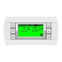
Press and to position on sub-menu and con-
rm with . The following screen is displayed:
Press again to access the screen displaying the system serial
network state:
Chiller unit in network ON
Chiller unit in network OFF
Unit in network and declared present but not in opera-
tion (compressor ON)
Unit in network and declared present and in operation
(compressor ON)
Unit in network and declared present and in alarm status
The menu and relative sub-menus allow conguring the
system. Enter the manufacturer password (using and ) and
press .
Sub-menu
Number of units set (maximum 10)
Type of unit
Rotation type (TIME, USER, FIXED)
Connection time among different units
= The unit activation depends on the operation hours (the unit
with less operation hours starts rst)
= The unit activation and deactivation sequence can be set.
= The unit activation and deactivation is xed (unit 1 is always
the unit that activates and deactivates rst).
Press the DOWN button to the form where you enter, you can set
the adjustment mode SEQUENTIAL (saturation drive) or PARALLEL
(saturation step) as well as the control probe OUTLET (outlet
temperature) or inlet (return temperature).
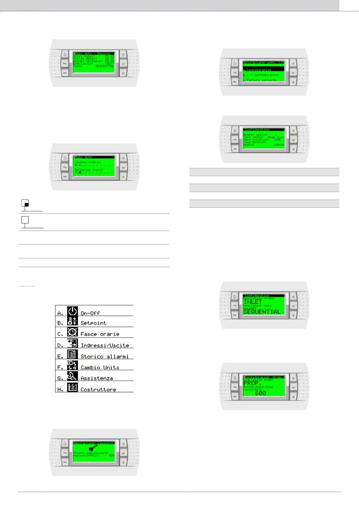
The following screen allows you to choose the type of control used to
calculate the number of units to be activated, ie proportional (Prop.)
or proportional and integral (Prop. + INT.). In the latter case, you can
dene the integration time.