86
Enclosed documents
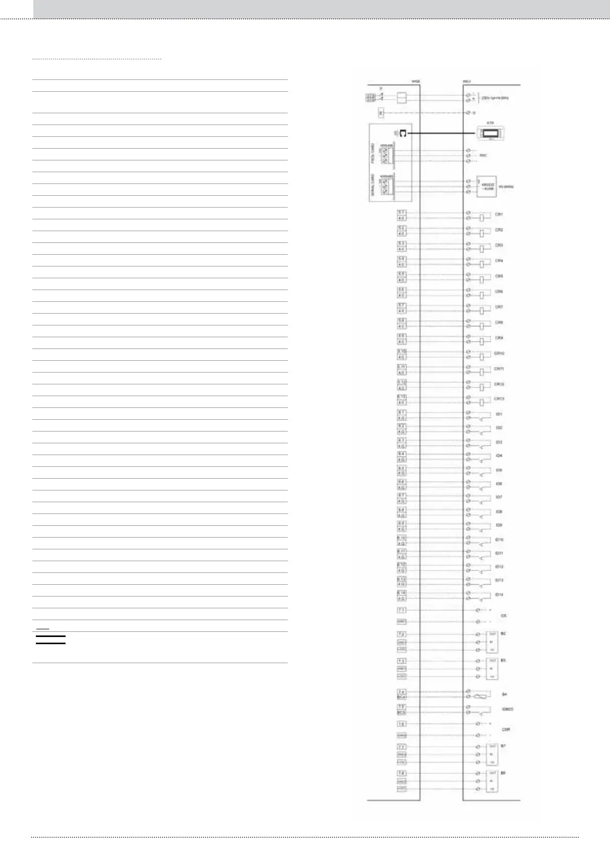
Electrical panel internal terminal board
User external terminal board
Manoeuvre master switch and differential protection
(30mA sensitivity )-automatic (25A)
Line
Neutral
Earth terminal;
RS485 serial interface (accessory);
6-way telephone connector (RJ12);
Remote keyboard (accessory);
Chiller serial network;
BMS and external BMS serial network;
Centralised remote On/Off
Centralised Summer/Winter
Requested recovery*
Double Set-point (primary)
Double Set-point (recovery);
System general alarm
Primary ow switch;
Rejection device ow switch (water/water vers.);
Primary pump alarm 1;
Primary pump alarm 1;
Rejection device pump alarm 1 (water/water vers.);
Rejection device pump alarm 2 (water/water vers.);
Recovery pump alarm 1 *;
Recovery pump alarm 2 *;
Primary pump 1;
Not used;
Not used;
Primary pump 2;
Not used;
Not used;
Rejection device pump 1 (water/water vers.);
Rejection device pump 2 (water/water vers.);
System general alarm
Chiller general alarm + serial network alarm;
Integrative/replacement boiler request;
Recovery pump 1 *;
Recovery pump 2 *;
Primary shifting Set-point (4÷20mA signal);
System return water temperature probe;
System ow water temperature probe;
Outdoor air temperature probe;
Recovery ow switch *;
Recovery shifting Set-point (signal 4-20mA) *;
Recovery return water temperature probe *;
Recovery ow water temperature probe *;
- - - Connection by installer
6-wire telephone cable
(maximum distance 50m, for greater distances contact
RHOSS S.p.A. customer service)
◦◦ The electrical panel is accessible from the front panel of the unit.
◦◦ Connections must be made in compliance with current standards
and with the diagrams provided with the machine.
◦◦ Machine earthing is legally compulsory.
The following diagrams only show the connections to be made by
the installer.
For electrical connections to the unit and the accessories, follow the
wiring diagrams which are supplied with them.
only for EXP units