Chapter 2 Installation and Confirmation
2-3 Descriptions of Terminal and Wiring Diagram
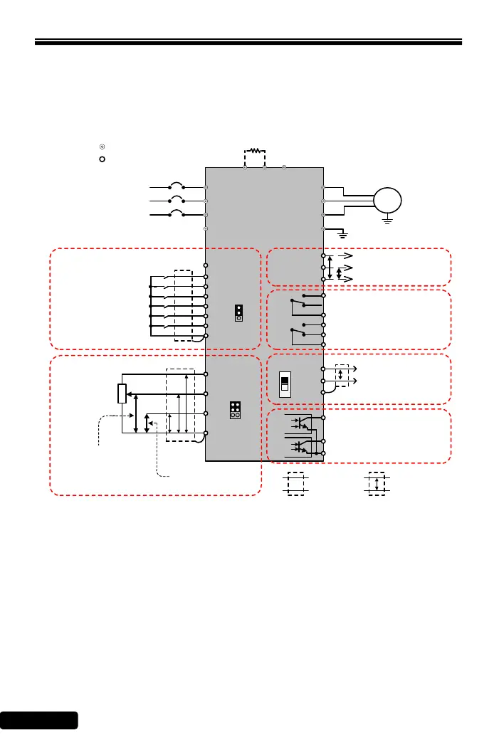
2-3-1 Wiring Diagram
Model: RM6F5-2001 ~ RM6F5-2005;
RM6F5-4001~RM6F5-4007
RM6F5
IM
SINK
SOURCE
I
V
FWD
REV
X1
X2
X3
X4
12V
Vin
Iin
GND
CME
Y2
Y1
Tc1
Tb1
Ta1
Tc2
Ta2
FM+
AM+
R/L1
S/L2
W/T3
V/T2
G
U/T1
P
R
P N
Shielded
Wire
Twisted-Pair
Shielded Wire
P
P P P
VR 1KΩ,1/4W
Forward
Reverse
Multi-function Input Terminal 1
Three-Phase, 50/60Hz
AC Power Input
Induction Motor
(-)
(+)
(+)
Multi-function Output Terminal
(Relay Type)
(AC 250V/0.5A COSθ=0.3)
Multi-function Output Terminal
(Open collector)
(DC 48V/50mA)
Main Circuit Terminals
Control Terminals
※2
T/L3
Braking Resistor(option)
GND
Analog Output Terminal
(DC 0~10V)
※1
COM
R/L1
S/L2
Current Input for
Frequency Setting
(Default: DC 4~20mA)
Voltage Input for
Frequency Setting
(Default: DC 0~10V)
JP4
Multi-pump Control Terminal
P
DX+
DX-
FG
P24
JP5
ON
1
DSW3
Multi-function Input Terminal 2
Multi-function Input Terminal 3
Multi-function Input Terminal 4
G
T/L3
※3
※1.JP5: SINK / SOURCE selection;
The signal input selection of multi-function input terminal, please see the
section 2-3-2 SINK / SOURCE Definition
※2.JP4: I / V selection;
I position: Iin-GND terminal is inputted with the current signal.(default)
V position: Iin-GND terminal is inputted with the voltage signal.
※3.DSW3: The terminal resistor selection for multi-pump control: The internal
resistance is 100Ω.
※4.The analog input selection is set by F_126 (default: DC 2~10V(4~20mA))
※5.Tightening torque is 5 lb-in(5.7 kgf-cm)
 Loading...