Chapter 2 Installation and Confirmation
2-4-2 Dual & Multi-pump Control (E-mode
、
F-mode
、
M-mode)
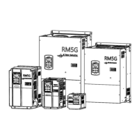
Wiring 1 (standard wiring)
Drive #0
- +
Drive #1
- +
Drive#2
- +
ON
I
V
I
V
I
V
Pressure
transducer
Drive#3
- +
I
V
DSW3
JP4 JP4 JP4 JP4
1
ON
DSW3
1
ON
DSW3
1
ON
DSW3
1
P24
Iin
DX+ DX- FG
P24
Iin
DX+ DX- FG
P24
Iin
DX+ DX- FG
P24
Iin
DX+ DX- FG
JP1 JP1 JP1 JP1
Pressure
transducer
Pressure
transducer
Pressure
transducer
※( Dotted line: more than three pumps according customer requirement to set up )
(Selection of Parallel Control
Mode)
=2 (E-mode) or
=3 (F-mode) or
=4 (M-mode)
(Set Drive’s No. in Parallel
Control)
Impedence selection of Iin
(Open﹕500Ω;Close﹕250Ω)
Input signal type selection of Iin
(Voltage/Current)
Auxiliary Drive #1(#2,#3)
(Selection of Parallel Control
Mode)
=2 (E-mode) or
=3 (F-mode) or
=4 (M-mode)
(Set Drive’s No. in Parallel
Control)
Impedence selection of Iin
(Open﹕500Ω;Close﹕250Ω)
Input signal type selection of Iin
(Voltage/Current)
#1, #2: 1 position
#3: ON position
※Note: Dual drive (or multi-drive) uses a set of pressure sensor independently.(Suggest
that using this wiring standard)
 Loading...