Chapter 2 Installation and Confirmation
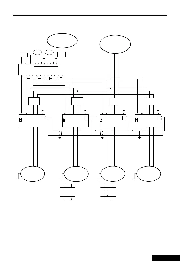
2-4-3 Multi-pump Use of ACE-S12 Signal Distributor Control
Iin
GND
R S T
U V W
Drive#1
R S T
U V W
R S T
U V W
R S T
U V W
NFB
NFB
NFB
NFB
Meter
PE
PE
PE
PE
I
V
I
V
I
V
I
V
L N
ACE - S12
DX+
DX-
DX+
DX-
DX+
DX-
DX+
DX-
PT2 PT1
泵浦馬達泵浦馬達泵浦馬達泵浦馬達
P P P
隔離線 雙絞隔離線
P
Iin
GND
Iin
GND
Iin
GND
AO1+ AO1- FG AO2+ AO2- FG AO3+ AO3- FG AO4+ AO4- FG
AO5+
AO5-
FG 24V Iin G24 FG 24V Iin G24 FG
NFB
Drive#2Drive#0
Drive#3
Note:
1. ACE-S12 signal distributor can be made input current signal covert into DC voltage,
meanwhile, distributing five set of output (output can switch current DC:4~20mA or DC: 0~10V
signal). To reach constant pressure, output signal will distribute the signal to drives(maximum: 4
drives).
2. Wiring: First, pressure sensor connect PT1 , and alternative pressure sensor connect PT2.
AC
power
 Loading...