Chapter 5 Parameter Setting Description
5-8 Multi-Function Input Setup
Multi-function Input Terminal (X1)
Multi-function Input Terminal (X2)
Multi-function Input Terminal (X3)
Multi-function Input Terminal (X4)
a. “+” represents positive logic (N.O; contact a)
b. “-” represents negative logic (N.C; contact b)
c. Multi-function terminals X1 ~ X4 can be set to perform following functions:
0: As F_015 = 4 (Under draining multi-pump control mode ), F_052、F_053、F_054=0.
Pump start/stop control by multi-input terminal (X1,X2,X3). This funtion is suggested
to be used, drive will start/stop in sequence when any terminal is activated.
±1: Jog command (refer to F_039)
±2: Secondary accel/decel time command (refer to F_027, F_028)
±3: Multi-speed level 1 command (refer to F_032 ~ F_038)
±4: Multi-speed level 2 command (refer to F_032 ~ F_038)
±5: Multi-speed level 3 command (refer to F_032 ~ F_038)
±6: Reset command
When the drive trips to stop, executing reset command can clear the fault
±7: External fault command (thr)
a. When the terminal received the fault command during operation, drive trips to stop.
b. This function is disabled when the drive at stop condition
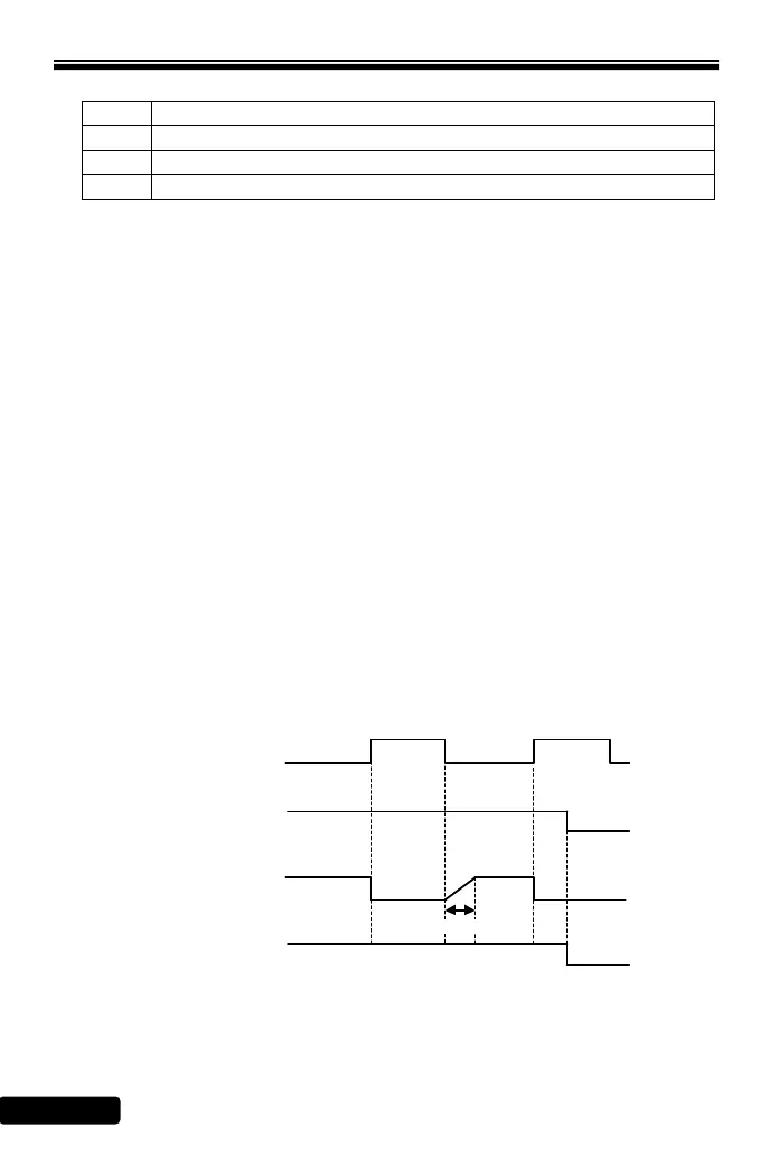
±8: Interruption of output command (bb)
The parameter can interrupt the output voltage of drive.
Interruption of output command (F_054=8)
Output voltage
Output frequency
Interruption of
output command
(X3)
Start command
0.3 sec
 Loading...