32DF9T02.C
4 - 9
c. Raise platform to vehicle floor height using control pendant ( /UP), and then support.
WARNING!
•• WEAR PROTECTIVE CLOTHING AND EYE PROTECTION AT ALL TIMES. BAT-
TERIES CONTAIN ACID THAT CAN BURN. IF ACID COMES INTO CONTACT
WITH SKIN, IMMEDIATELY FLUSH AFFECTED AREA WITH WATER AND WASH
WITH SOAP.
•• WORK IN A PROPERLY VENTILATED AREA. DO NOT SMOKE OR USE AN
OPEN FLAME IN THE VICINITY OF BATTERY.
••• •
DO NOT LAY ANYTHING METALLIC ON TOP OF BATTERY.
d. Disconnect positive battery cable at vehicle battery compartment.
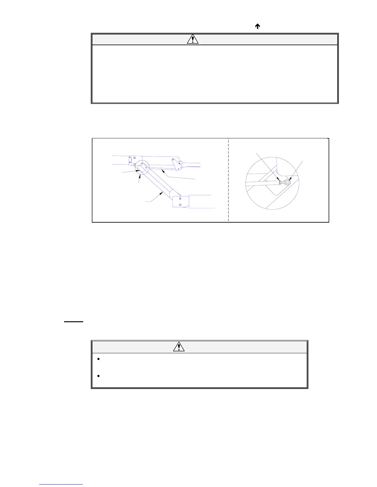
e. Refer to
Figure 4-12. View A-A is from beneath platform. Locate right-side actuator rod assem-
bly (right-hand side of platform, at top of lifting frame). Loosen rod-end jam-nut.
f. Remove shoulder bolt that fastens actuator rod-end to mounting plate (on lifting frame); catch
spacer as it falls.
g. Repeat for left-side actuator rod assembly.
h. Fold bridgeplate onto lift platform, and rotate actuator arms parallel to platform. Secure bridge-
plate and actuator arms to platform with cable ties.
i. Remove right and left rollstop side covers (four screws and washers) and spacers.
j. Disconnect electrical harnesses at both sides of platform (rollstop switch harness at left; rollstop
motor harness at right). Cut black and white leads to the safety belt switch; cut leads adjacent to
factory-crimped butt splices. Remove cable ties that hold harnesses in place. Remove connec-
tors from harnesses.
NOTE: Record connector pin position for each wire. This data will be used for platform re-installation;
refer to wiring diagrams in
Chapter 3. Crimp safety belt switch leads to harness with new butt
splices when re-installing.
CAUTION!
Double-check platform support before removing lower mounting pins.
The platform will be free to rotate after pins are removed.
Do not damage outside surface of pins during removal. A pin should be
replaced if its outer surface is pitted or grooved after removal.
FIGURE 4-12: BRIDGEPLATE ACTUATOR ROD REMOVAL
SHOULDER BOLT
JAM-NUT
SPACER
ACTUATOR
ASSEMBLY
ROD
VIEW A-A
VIEW A-A
RIGHT-SIDE
MOUNTING
PLATE
LIFTING
FRAME
&
 Loading...