32DF9T02.C
4 - 17
c. DRIVE CHAIN ADJUSTMENT
NOTE:
Adjust final drive chain first when adjusting both drive chains. The primary drive chain ad-
justment is dependent on setting of final drive chain.
Final Drive Chain
1) Refer to LIFT SERVICE ACCESS section to deploy platform and open service access
panel.
2) Refer to
Figure 4-18. Loosen screws fastening intermediate shaft bracket to carriage. The
front screw is accessible from top of lift, and rear screw is accessible through service hatch
(use an open end wrench above intermediate shaft mounting bracket to hold nut).
3) Refer to
Figure 4-17. Loosen the two nuts fastening gearmotor assembly to carriage.
4) Verify that motor retaining clamp (fastens gearmotor to gearmotor support) is tight.
5) Move gearmotor assembly toward driveshaft to slacken chain; a small pry bar may be in-
serted between motor and front of carriage for leverage.
NOTE: DO NOT FORCE THE GEARMOTOR. Loosen the two gearmotor nuts further, or loosen
motor retaining clamp, to obtain more movement.
6) Adjust chain tension to achieve .030" (.8mm) slack on lower span.
7) Tighten screws fastening intermediate shaft bracket to carriage.
8) Refer to PRIMARY DRIVE CHAIN ADJUSTMENT, if adjusting both chains. Otherwise, con-
tinue.
9) Raise service access panel, and install two retaining screws and lock-nuts at front edge of
panel.
10) Reconnect positive battery cable at vehicle battery compartment.
Primary Drive Chain
1) Refer to LIFT SERVICE ACCESS section to deploy platform and open service access
panel.
2) Refer to
Figure 4-17. Loosen motor retaining clamp.
3) Loosen two nuts fastening gearbox to carriage.
4) Move gearmotor assembly toward driveshaft to slacken chain; a small pry bar may be in-
serted between motor and front of carriage for leverage.
NOTE: DO NOT FORCE THE GEARMOTOR. Loosen two gearmotor retaining nuts further, or
loosen motor retaining clamp further to obtain more movement.
5) Refer to
Figure 4-18. Adjust chain tension to achieve .030" (.8mm) slack on upper span.
6) Tighten nuts fastening gearmotor to carriage.
7) Tighten motor retaining clamp.
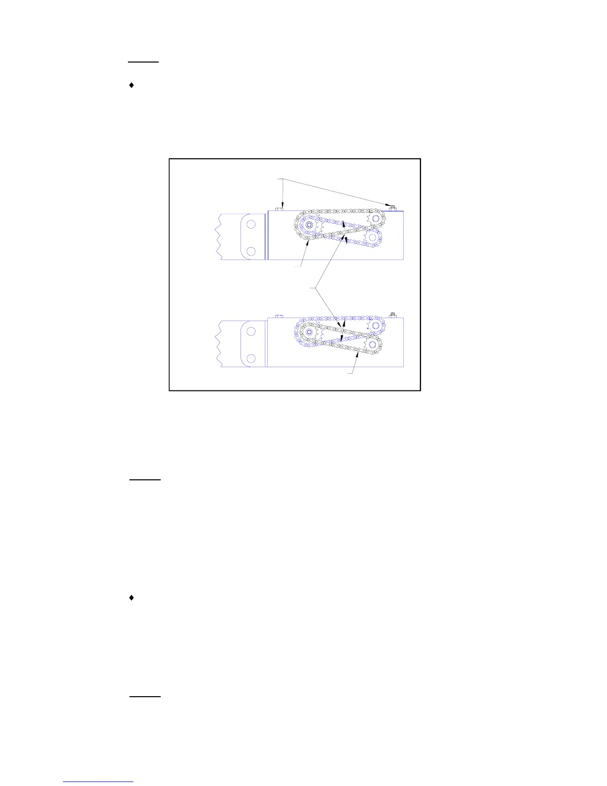
FIGURE 4-18: DRIVE CHAIN SLACK ADJUSTMENT
PRIMARY DRIVE CHAIN
FINAL DRIVE CHAIN
BRACKET RETAINING SCREWS
INTERMEDIATE SHAFT
0.030" (0.8mm) TOTAL SLACK
 Loading...