15
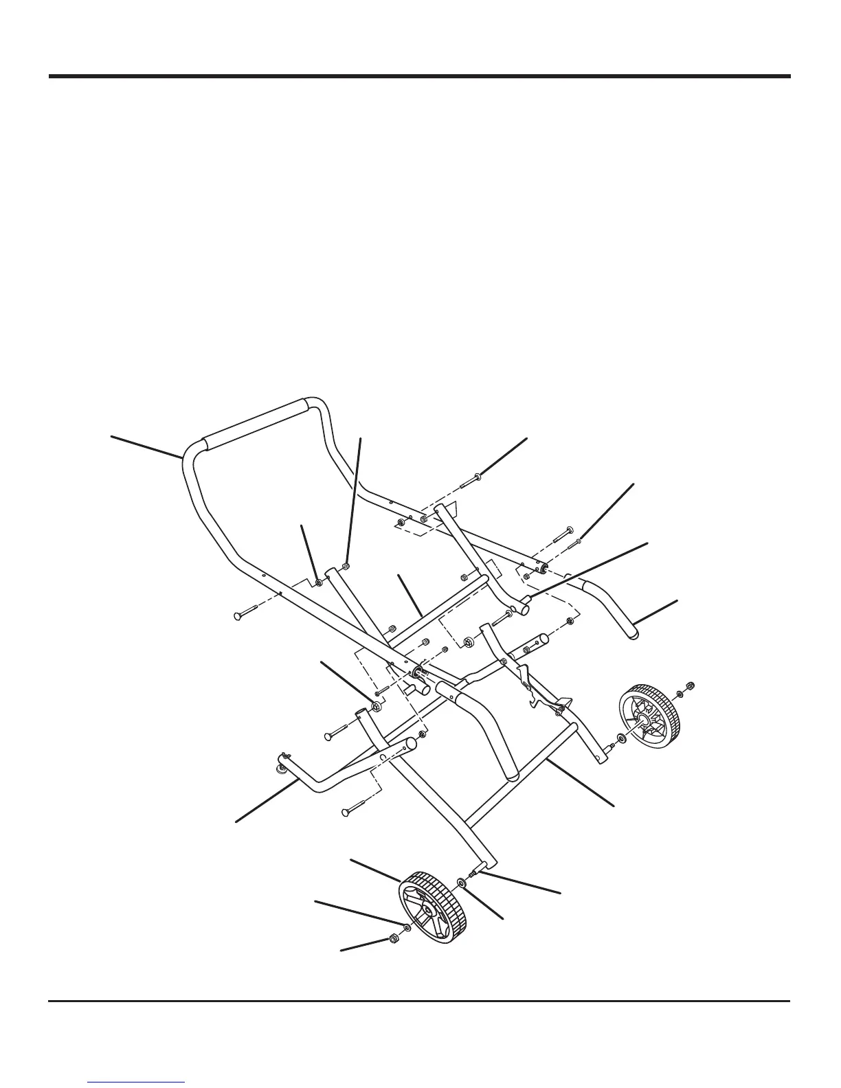
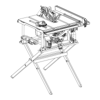
ASSEMBLING THE LEG STAND
See Figure 7.
Many of the leg stand parts are movable. All hardware must
be tightened securely but not so tight that the leg stand won’t
open and close. For easier assembly, match letter to letter
and fingertighten all fasteners. Only tighten fasteners securely
when you are sure the release lever locks over the stop pin.
Align handle with holes in the end of the upper tube and
insert. Secure in place using a screw. Repeat for other side.
Place the center brace on top of the inner leg assembly
(curve side up) with the stop pin under the pedal assembly
latch.
NOTE: The stop pins rest on top of inner leg assembly.
ASSEMBLY
Fig. 7
SMALL
SPACER
LOCK
NUT
UPPER
TUBE
INNER LEG
ASSEMBLY
CENTER
BRACE
AXLE
LOCK
NUT
FLAT WASHER,
SMALL
STOP
PIN
WHEEL
OUTER
TUBE
CARRIAGE
BOLT
FLAT WASHER,
LARGE
Insert a carriage bolt through the top hole of the inner leg
assembly then slide a large spacer on the bolt. Repeat
for the other side.
Slide the center brace onto the bolt and secure in place
using a lock nut. Repeat for the other side.
With the curve handle turned downward, secure the up-
per tubes to the leg stand using carriage bolts, spacers,
and lock nuts.
Slide the flat washer (large), wheel, and flat washer (small)
onto the axle through the hole in the center of the wheel.
Secure in place using lock nut.
Repeat with the second wheel.
Before use, verify the release lever locks the leg stand
securely. If the leg stand will not lock, do not use; contact
an authorized service center for assistance.
LARGE
SPACER
HANDLE
SCREW