34
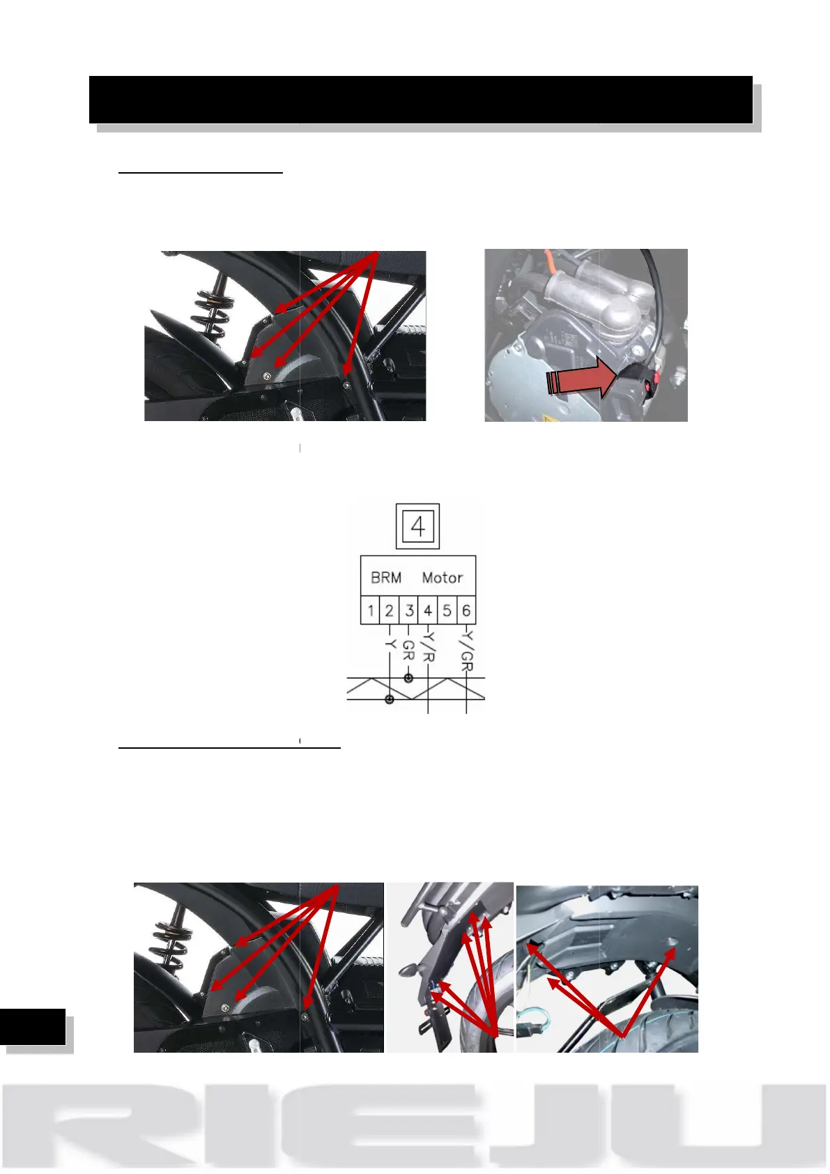
Check CAN drive unit:
CAN drive unit
sides, removing 7
1. Chec
k that the connector is correctly plugged
2.
Check the continuity of the wires
Check DC/DC 48V connector:
DC/DC is placed up to the rear fender, to access it:
1)
Remove the motor cover, both sides, removing 7 screws.
2)
Remove the metal real support fender, rem
3)
Remove rear plastic fender, removing 6 screws.
on the electrical motor. Remove the
k that the connector is correctly plugged
Check the continuity of the wires
Check DC/DC 48V connector:
DC/DC is placed up to the rear fender, to access it:
Remove the motor cover, both sides, removing 7 screws.
Remove the metal real support fender, rem
oving
Remove rear plastic fender, removing 6 screws.
Remove the motor cover, both sides, removing 7 screws.