159
START CONDENS 25 - 29 Kis
marone
blu
V Hv
1
2
6
1
CN2
marrone
blu
2
1
3
5
4
B
D
A
1 2 43
OPEOPE
rosa
blu
P
marrone
N
L
230 V
M3
F
blu
blu
marrone
marrone
marrone
blu
7
1
CN9
P.A.
2
3
1
S.S.
F.L.
bianco
bianco
rosso
rosso
viola
viola
-t°
3V
2
N
1
San.
3
Risc.
nero (san.)
marrone (risc.)
blu
3
1
CN4
TSC2
blu
E.A.
marrone
giallo/verde
N
F
CN1
3
1
2
rosso (+)
blu (HS)
rosa (PWM)
grigio (-)
CN10
V Lv
1
4
1
12
CN11
bianco
bianco
S.M.
-t°
-t°
S.R.
rosso
rosso
-t°
S.F.
grigio
grigio
nero
T.L.A.
blu
blu
bianco
CN8
CN7
1
12
CN11
1
4
CN10
1
7
CN9
CN6
CN5
CN12
1
CN4
1
3
CN3
1
2
CN2
1
6
AKL05 GAR
CN1
1
FA1
FA2
arancione
E.R.
JP1
JP2
JP3
JP4
JP5
JP6
JP7
JP8
CN15
P3
P2
P1
CN13
CN14
SW1
P4
F1
3.15A T
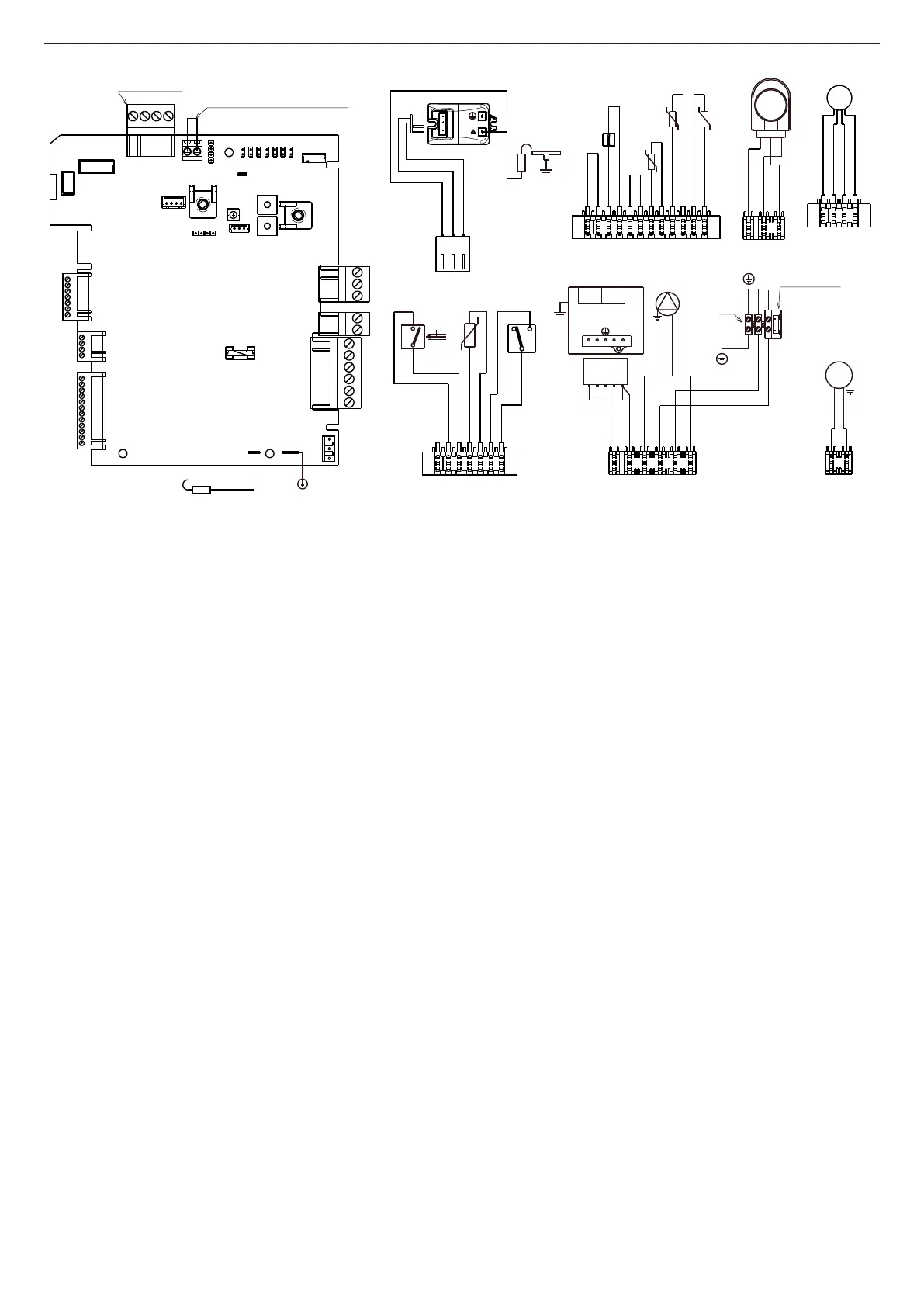
[IT] - Schema elettrico
LA POLARIZZAZIONE L-N È CONSIGLIATA
A Termostato ambiente: contatto privo di
tensione
B Valvola gas
C CN6 ove previsto
D Fusibile 3.15A F
AKL05GAR Scheda comando con visualizzatore
digitale integrato
P1 Potenziometro selezione off – estate –
inverno – reset / temperatura riscaldamento
P2 Potenziometro selezione set point
sanitario, abilitazione/disabilitazione
funzione PRERISCALDO (solo in
configurazione COMBI)
P3 Preselezione curve di termoregolazione
P4 Non usato
JP1 Abilitazione manopole frontali alla taratura
del solo massimo riscaldamento (MAX_
CD_ADJ)
JP2 Azzeramento timer riscaldamento
JP3 Abilitazione manopole frontali alla taratura
in service (MAX, MIN, MAX_CH, RLA)
JP4 Selettore termostati sanitario assoluti
JP5 Funzionamento solo riscaldamento con
predisposizione per bollitore esterno e
termostato
JP6 Abilitazione funzione compensazione
notturna e pompa in continuo
JP7 Abilitazione gestione impianti standard/
bassa temperatura
JP8 Abilitazione gestione flussostato (jumper
inserito)/flussimetro (jumper non inserito)
S.W. Spazzacamino, interruzione ciclo di sfiato e
taratura quando abilitata
E.R. Elettrodo rilevazione fiamma
F1 Fusibile 3.15A T
F Fusibile esterno 3.15A F
M3 Morsettiera collegamenti esterni
P Pompa
OPE Operatore valvola gas
V Hv Alimentazione ventilatore 230 V
V Lv Segnale controllo ventilatore
3V Servomotore valvola 3 vie
E.A. Elettrodo accensione
TSC2 Trasformatore accensione
F.L. Flussostato sanitario
S.S. Sonda (NTC) temperatura circuito sanitario
P.A. Pressostato acqua
T.L.A. Termostato limite acqua
S.F. Sonda fumi
S.M. Sonda mandata temperatura circuito
primario
S.R. Sonda ritorno temperatura circuito primario
CN1-CN15 Connettori di collegamento (CN6
kit sonda esterna/pannello comandi
– CN7 kit valvola di zona - CN5
termostato ambiente
[EN] - Wiring diagram
L-N POLARISATION IS RECOMMENDED
Bianco=White • Blu=Blue • Grigio=Grey •
Marrone=Brown • Nero=Black • Rosso=Red •
Viola=Violet
A Room thermostat jumper (voltage free
contact input)
B Gas valve
C CN6 when expected
D Fuse 3.15A F
AKL05GAR Control card with integrated digital
display
P1 Potentiometer to select off - summer -
winter – reset / heating temperature
P2 Potentiometer to select domestic hot water
set point, and enable/disable PREHEATING
function (in COMBI configuration only)
P3 Thermoregulation curve preselection
P4 Not used
JP1 Enable front knobs for calibration of
maximum heating only (MAX_CD_ADJ)
JP2 Heating timer reset
JP3 Enable front knobs for calibration in service
(MAX, MIN, MAX_CH, RLA)
JP4 Absolute domestic hot water thermostat
selector
JP5 Heating only function selection with
provision for external storage tank with
thermostat or probe
JP6 Enable night-time compensation function
and continuous pump
JP7 Enable management of low temperature/
standard installations
JP8 Enabling management of flow switch
(Jumper inserted )/flow meter (Jumper not
inserted)
S.W. Chimney sweep, interruption of venting
cycle and calibration when enabled
E.R. Flame detection electrode
F1 Fuse 3.15A T
F External Fuse 3.15A F
M3 External connections terminal board
P Pump
OPE Gas valve operator
V Hv Fan power supply 230 V
V Lv Fan control signal
3V 3-way valve servomotor
E.A. Ignition electrode
TSC2 Ignition transformer
F.L. DHW flow switch
S.S. DHW circuit temperature (NTC) probe
P.A. Water pressure switch
T.L.A. Water limit thermostat
S.F. Flue gases probe
S.M. Delivery temperature probe on primary
circuit
S.R. Return temperature probe on primary circuit
CN1-CN15 Connectors (CN6 external probe/
control panel kit – CN7 zone valve kit -
CN5 ambient thermostat
[FR] - Schéma électrique
LA POLARISATION L-N EST CONSEILLÉE
Bianco=Blanc • Blu=Bleu • Grigio=Gris •
Marrone=Marron • Nero=Noir • Rosso=Rouge
• Viola=Violet
A Shunt thermostat d’ambiance (contact sec)
B Vanne gaz
C CN6 si nécessaire
D Fusible 3,15 A F
AKL05GAR Carte de commande avec afficheur
numérique intégré
P1 Potentiomètre de sélection OFF – été
– hiver – réinitialisation/température
chauffage
P2 Potentiomètre de sélection point de
consigne sanitaire, activation/désactivation
fonction de PRÉCHAUFFAGE (uniquement
en configuration COMBI)
P3 Présélection courbes de régulation
thermique
P4 Non utilisé
JP1 Activation poignées avant haut réglage
chauffage maximal seul (MAX_CD_ADJ)
JP2 Remise à zéro du temporisateur
JP3 Activation des poignées avant au réglage
en service (MAX, MIN, MAX_CH, RLA)
JP4 Sélecteur des thermostats sanitaires
absolus
JP5 Fonctionnement chauffage seul avec pré-
équipement pour chauffe-eau extérieur et
thermostat
JP6 Activation de fonction de compensation
fonction de compensation nocturne et
pompe en continu
JP7 Activation de la gestion d’installations
standard/basse température
JP8 Activation de la gestion du fluxostat (jumper
inséré)/débitmètre (jumper non inséré)
S.W. Ramonage, interruption du cycle de purge
et réglage si activé
E.R. Électrode de détection de flamme
F1 Fusible 3,15 A T
F Fusible extérieur 3,15 A F
M3 Bornier de branchements extérieurs
P Pompe
OPE Opérateur vanne gaz
V Hv Alimentation du ventilateur 230 V
V Lv Signal de contrôle ventilateur
3V Servomoteur vanne à 3 voies
E.A. Électrode d’allumage
TSC2 Transformateur d’allumage
F.L. Fluxostat sanitaire
S.S. Sonde (NTC) température circuit sanitaire
P.A. Pressostat d’eau
T.L.A. Thermostat limite d’eau
S.F. Sonde de fumées
S.M. Sonde refoulement temp. circuit primaire
S.R. Sonde retour temp. circuit primaire
CN1-CN15 Connecteurs de branchement (CN6
kit sonde extérieure/panneau de
commande – CN7 kit vanne de zone
- CN5 thermostat d’ambiance