24
START CONDENS 25 - 29 Kis
During manufacture, the boiler is configured for standard systems.
Jumper Description
JP1 Calibration (Range Rated)
JP2 Heating timer reset
JP3 Calibration (see paragraph “Adjustments”)
JP4 Absolute domestic hot water thermostat selector
JP5 Do not use
JP6 Enable night-time compensation and continuous pump
function (only with outdoor probe connected)
JP7 Enable standard system/low temperature management
(see above)
JP8 Do not use
2.8 - Gas connection
The connection of the START CONDENS Kis boiler to the gas supply
must be carried out in the respect of current installation standards.
Before carrying out the connection, it is necessary to ensure that:
• The gas type is suitable for the appliance
• The piping is thoroughly clean.
9 The gas feeding system must be adapted to the boiler output
and must be equipped with all the safety and control devices pre-
scribed by the current standards. The use of a filter of adequate
dimensions is recommended.
9 Once the installation is done, check that the junctions carried
out are sealed.
2.9 - flue gas outlet and combustion air suction
9 The maximum lengths of the ducts refer to flue systems availa-
ble in the catalogue.
67,5 135 72 130,5
130
175
Suction/discharge pipes length table
Maximum straight
length
Pressure drop
25 Kis 29 Kis bend 45° bend 90°
Flue gases pipe
Ø 80 mm ("forced open”
installation) (type B23P-
B53P)
70m 65m 1m 1.5m
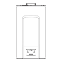
Concentric pipe
Ø 60-100 mm (horizontal)
5.85m 4.85m 1.3m 1.6m
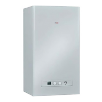
Concentric pipe
Ø 60-100 mm (vertical)
6.85m 5.85m 1.3m 1.6m
Concentric pipe
Ø 80-125 mm
15.3m 12.8m 1m 1.5m
Twin pipe Ø 80 mm 45+45 m 40+40 m 1m 1.5m
9 The straight length measurement is inclusive of the first bend
(boiler connection), terminals and joints; with the exception of
the vertical coaxial duct Ø 60-100 mm, where the straight length
does not include the bends.
9 It is compulsory to use specific pipes.
9 The non insulated flue gas outlet pipes are potential sources of
danger.
9 The use of a longer pipe causes a loss of output of the boiler.
9 Make sure the flue gas discharge pipe is tilted 3° towards the
boiler.
3°
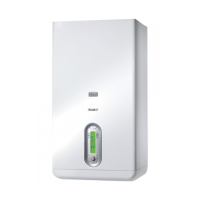
Flue gases pipe Ø 80 mm ("forced open” installation) (type
B23P-B53P)
262,5
The appropriate adaptor kit must be installed for this configuration.
The concentric pipes can be fitted in most suitable direction in rela-
tion to installation requirements. For installation, follow the instruc-
tions supplied with the specific kit for condensing boilers.
Concentric pipes ø 60-100mm
130
100
Twin pipes ø 80mm
134
134
87
129
Air inlet adaptor kit
Ø 80 mm
Air inlet adaptor kit
from Ø 60 mm to
Ø 80 mm
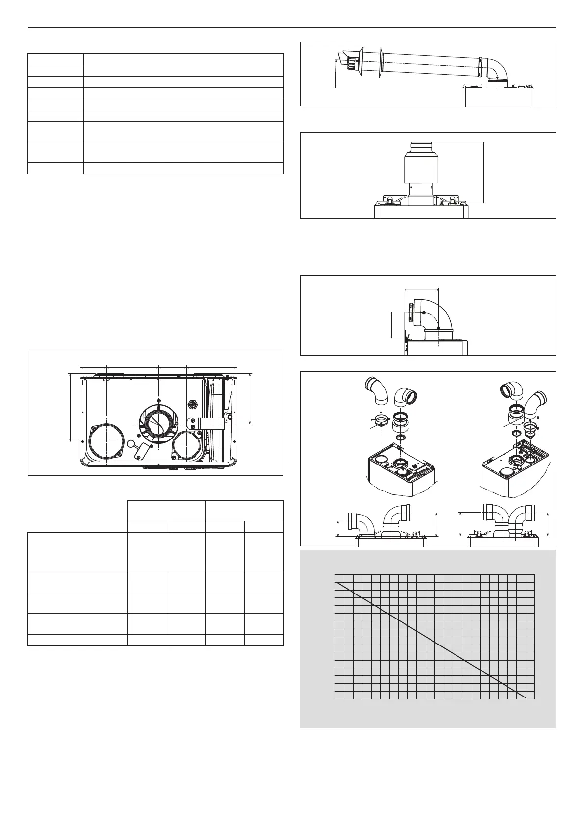
Maximum pipe length Ø 80 mm - 25 KIS
0
10
20
30
40
50
60
70
80
0 5 10 1 5 20 25 30 35 40 45 5 0 55 60 65 70 75 80 8 5 90 95 100 10 5 110
Length of suction pipe (m)
Length of discharge pipe (m)