20136866
10
Technical description of the burner
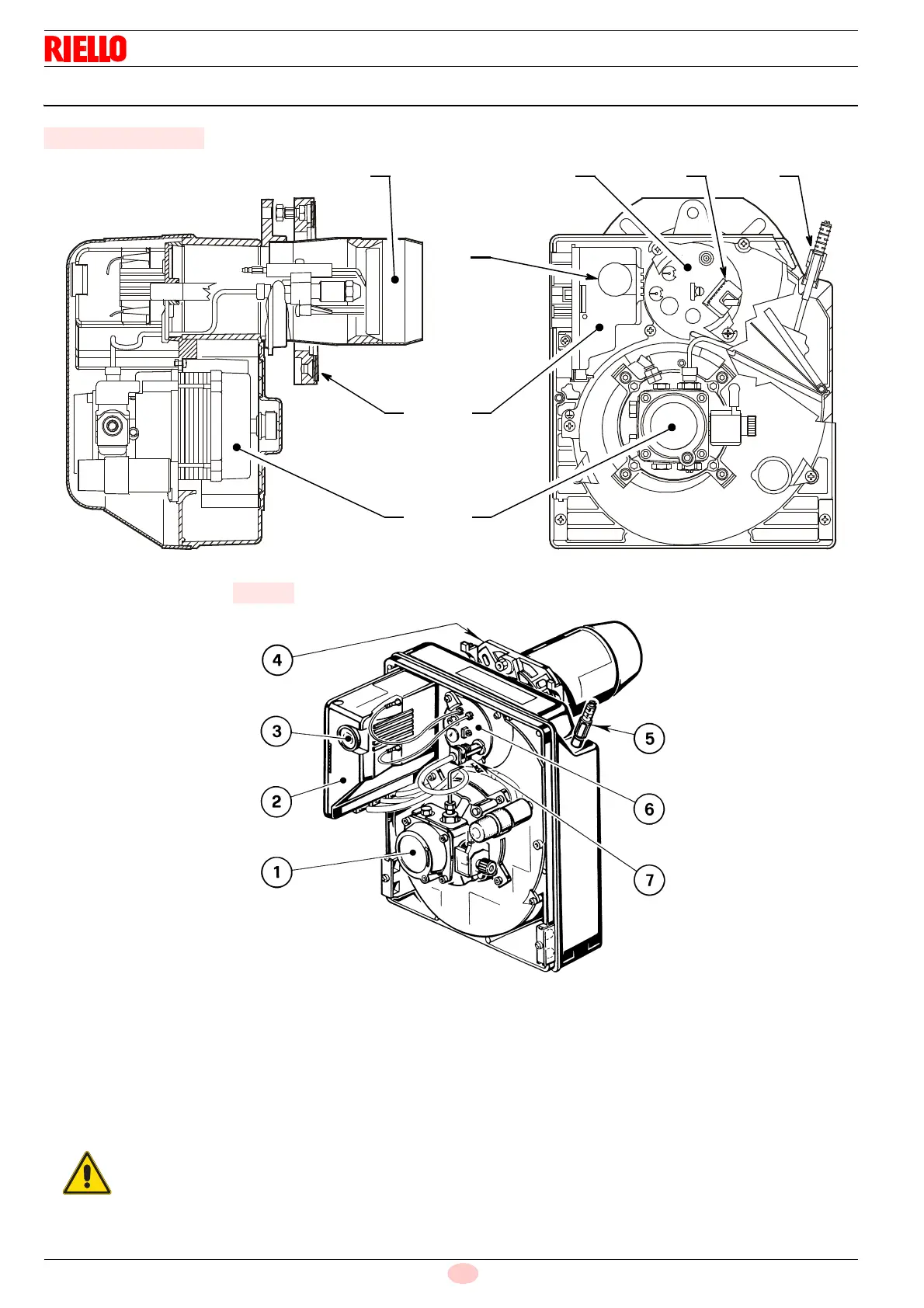
4.7 Burner description
1Oil pump
2 Control box
3 Reset button with lock-out signal
4 Flange with insulating gasket
5 Air damper adjustment assembly
6 Nozzle-holder assembly
7 Flame sensor
8Flame tube
9 Motor
Fig. 2
RG2 - RG3 - RG2F
RG1F
1
2
3
4
8
9
7 56
D4681
S7194
To meet the required standards, the burner must
be protected by a pane or by the boiler door.
This protection must be removed only with a tool.