20136866
24
Start-up, calibration and operation of the burner
6.1 Notes on safety for the first start-up
6.2 Combustion adjustment
In conformity with EN 267, the installation of the burner on the
boiler, the adjustment and testing must be carried out in compli-
ance with the instruction manual of the boiler, including control of
the CO and CO
2
concentration in the flue gases, their tempera-
ture and the average temperature of the water in the boiler.
To suit the required boiler output, choose the proper nozzle and
adjust the pump pressure and the air damper opening in accord-
ance with the following data.
The values in Tab. H are obtained on the boiler (according to
EN267).
They refer to 12.5 % CO
2
, at sea level and with an ambient and
light oil temperature of 20 °C.
Tab. H
6 Start-up, calibration and operation of the burner
The first start-up of the burner must be carried out
by qualified personnel, as indicated in this manual
and in compliance with the standards and regula-
tions of the laws in force.
Check the correct working of the adjustment, com-
mand and safety devices.
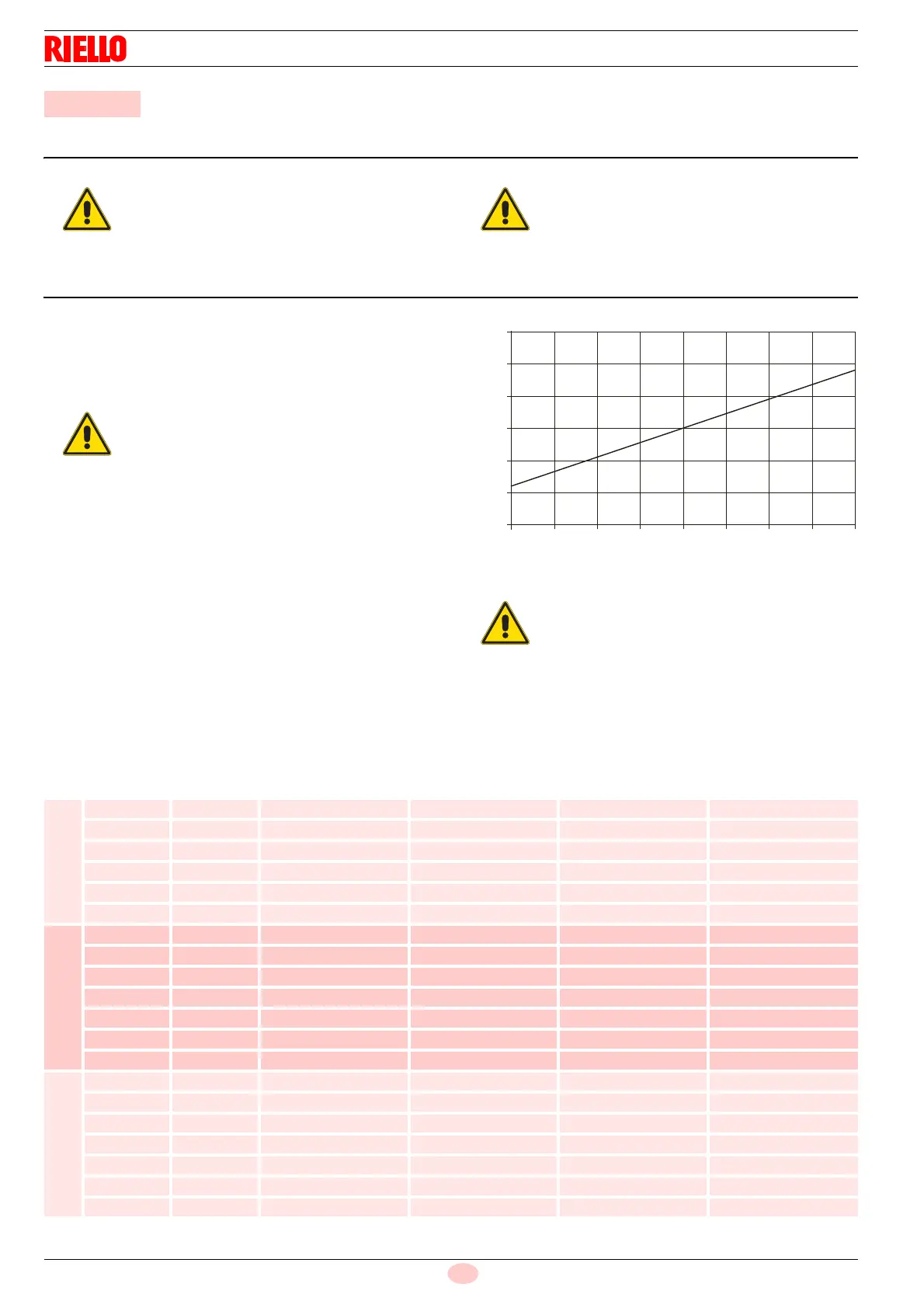
The temperature of the combustion air (relative to
the place where the burner is installed) may vary
during the season, it influences the CO
2
of the
burner. We recommend adjusting the CO
2
based
upon the temperature of the combustion air at the
time when the burner calibration is carried out in
accordance with what is shown in the following di-
agram.
Example Combustion air temperature =10°C ad-
just the CO
2
to 12.5%.
For the burners RG1F - RG2F
The values in the table are approximate; to ensure
the burner operates efficiently we suggest adjust-
ing the combustion head according to the require-
ments of the type of generator.
If operating at 60Hz it is necessary to recalibrate
the burner, closing the air damper to reduce the
amount of intake air.
Fig. 22
D4604
14.5
14.0
13.5
13.0
12.5
12.0
11.5
0 5 10 15 30
40
352520
% CO
2
Combustion air temperature
Nozzle
Pump
Pressure
Burner
output
Combustion head
adjustment
Air damper
adjustment
GPH Angle bar kg/h ± 4% Set-point Set-point
RG1F TL
0.65 60° 12 2.7 2.5 1.5
0.75 60° 12 3.0 3 2.9
0.85 60° 12 3.4 3.5 4.2
1.00 60° 12 4.0 4 5.6
1.10 60° 12 4.4 4 6.3
1.10 60° 15 5.0 4 6.7
RG2 - RG2F TL
1.00 60° 12 4.0 0 0.9
1.10 60° 12 4.4 1 3.1
1.25 60° 12 5.0 2 3.4
1.50 60° 12 6.0 3 3.8
1.75 60° 12 7.0 4 4.5
2.00 60° 12 8.0 5 4.9
2.25 60° 14 9.8 6 6.0
RG3
1.75 60° 12 7.0 0 1.3
2.00 60° 12 8.0 1 2.3
2.25 60° 12 9.0 3 2.6
2.50 60° 12 10.0 3.5 3.0
3.00 60° 12 12.0 5 3.5
3.50 60° 12 14.0 6 4.4
3.50 60° 14 15.2 6 5.6