29
20136866
Start-up, calibration and operation of the burner
6.7 Table of times
Tab. I
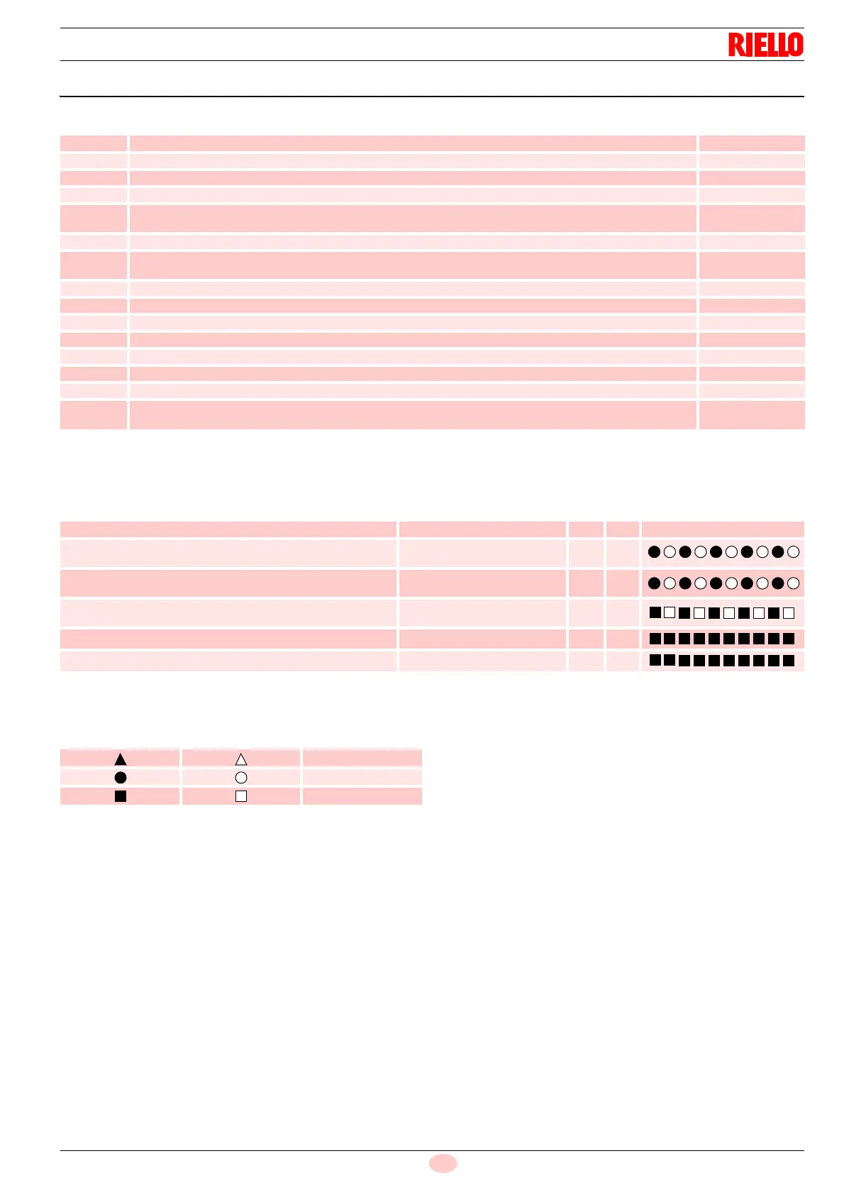
6.7.1 Operating status indication
Tab. J
Key
Tab. K
Symbol Description Value (sec.)
t0 Standby: the burner is waiting for a heat request -
t1 Standby time for an input signal: reaction time, control box remains in waiting mode for t1 2
t1l Flame or flame simulation detected before demand for heat: the control box remains idle. 25
t2 Initialisation standby time: checking time following the main power start-up 4.5
t2l
Checks extraneous light or parasite flame during t2: waiting mode for t2l, then lockout: the motor
does not start
25
t3 Pre-purging time: The fan motor is running, then the gas valve is activated 15
t3l
Checks extraneous light or parasite flame during pre-purging: control box goes into lockout at the
end of t3l
25
t3i Spark pre-ignition time 5
ts Safety time 5
t4i Total spark ignition time 15
t4l Reaction time to achieve safety deactivation due to flame loss 1
t5i Spark post-ignition time 3
- Minimum time to reset the control box using reset button 0.4
Minimum time to reset the control box using remote reset 0.8
tr
Re-cycles: max. 3 repeats of the complete start-up sequence in the case of flame loss during opera-
tion; the final action at the last attempt following flame failure is a lockout
3
re-cycles
Status
Reset button
colour
Seconds Colour code
Awaiting heat request - - - -
Awaiting heat request with continuous purging
ORANGE
Blink
0.5 2.5
Pre-purging, or long pre-purging
ORANGE
Blink
0.5 0.5
Safety time without flame
GREEN
Blink
0.5 0.5
Safety time with flame GREEN - -
Normal operating position GREEN - -
ON OFF Colour code
RED
ORANGE
GREEN