19
20136866
Installation
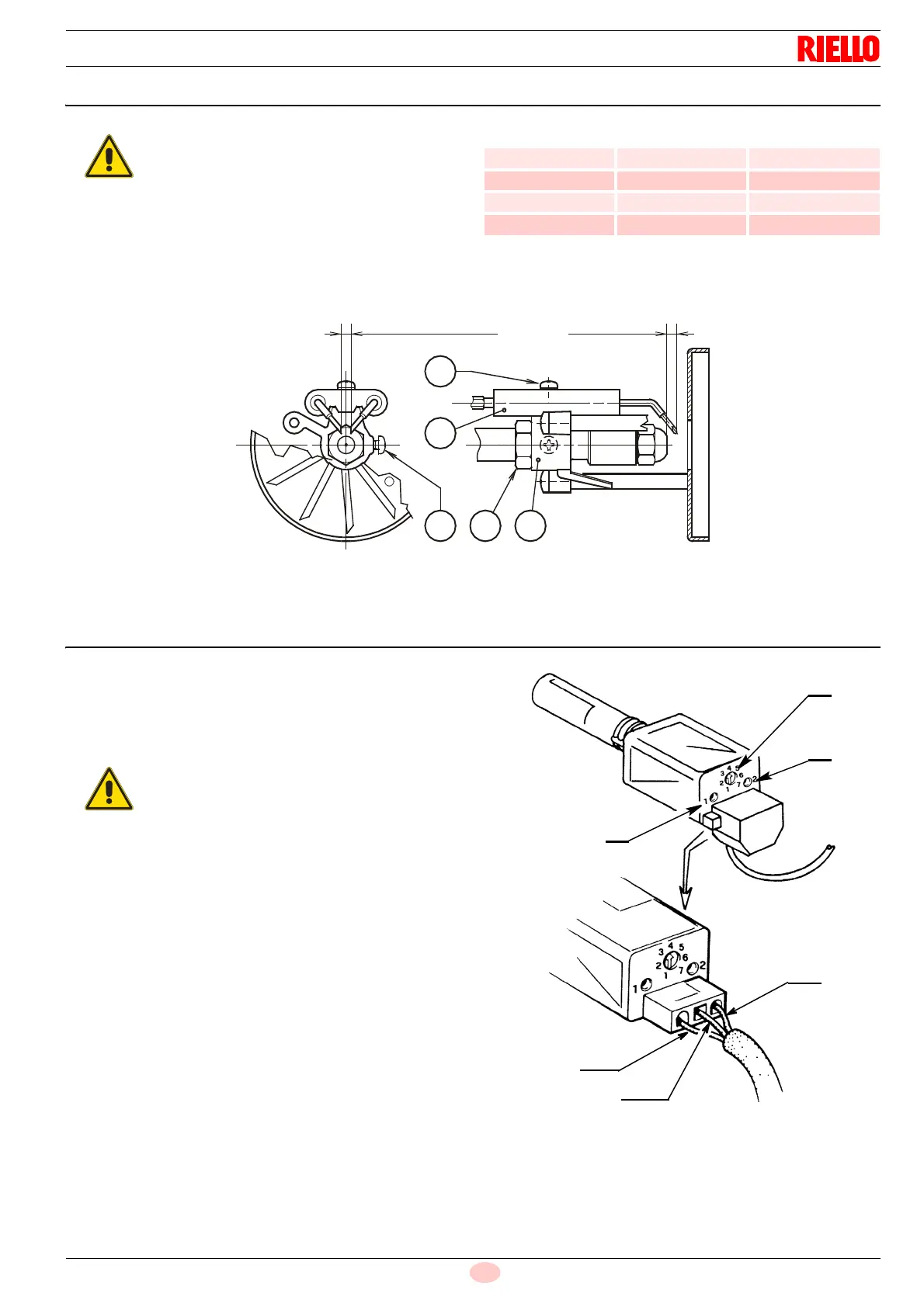
5.10 Electrodes setting
To adjust, proceed as follows:
rest the diffuser disc-holder assembly 1)(Fig. 13) on the noz-
zle-holder 2)(Fig. 13) and lock it with screw 3)(Fig. 13).
For any adjustments of the electrodes assembly 5),
loosen screw 4)(Fig. 13).
Tab. E
5.11 Flame sensor adjustment for burners RG1F - RG2F
The flame sensor leaves the factory calibrated to position 4.
It consists of:
a potentiometer 3)(Fig. 14) for adjusting the sensitivity.
Led 1)(Fig. 14) indicates the sensitivity.
Led 2)(Fig. 14) indicates its operation.
To adjust, proceed as follows:
turn the indicator of the potentiometer 3)(Fig. 14) anticlock-
wise until the LED 1)(Fig. 14) blinks, thereby defining the
minimum value of the notch.
Turn the indicator of the potentiometer 3)(Fig. 14) clockwise
until the LED 1)(Fig. 14) is on and fixed.
Consider the setting final as the minimum value detected by
increasing by one or two notches.
After a pause of at least five minutes, check that this adjust-
ment permits the proper start up of the burner.
These dimensions Fig. 13 must be respected.
Model A (mm) ± 0 B (mm)
RG2 4.5 - 0.5 4 5
RG3 4.5 - 0.5 6 7
RG1F 4.5 - 0.5 2.5 0.2
RG2F 4.5 - 0.5 4 5
During pre-purging the LEDs (1 and 2) stay
off.
Permanent operation is indicated when both
LEDs are lit up.
Fig. 14
Blue
Brown
Black
S7903
1
2
3