6 ProSYS Quick Programming Setup
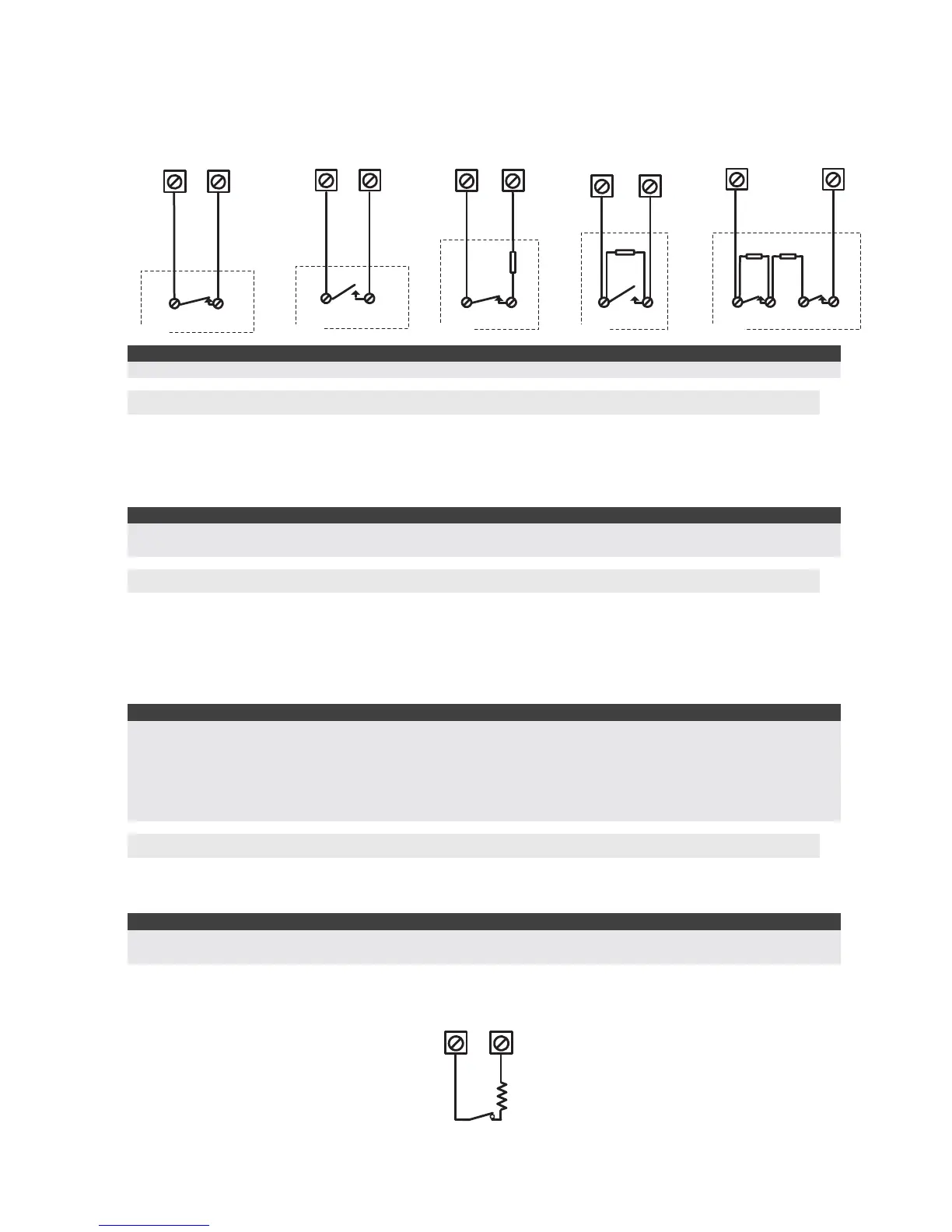
2.2 Connection on the main unit (ProSYS 5), Zone expanders (ProSYS EZ8,
EZ16)
END OF LINE ZONE
(N.O CONTACT)
zone com
ALARM
2.2 K
DETECTOR
NORMALLY OPEN ZONE
CONFIGURATION
ALARM
zone com
DETECTOR
NORMALLY CLOSED
ZONE CONFIGURATION
ALARM
zone
com
DETECTOR
END OF LINE ZONE
(N.C CONTACT)
2.2 K
zone com
ALARM
DETECTOR
DOUBLE END OF LINE
ZONE CONFIGURATION
com
2.2 K
ALARM TAMPER
zone
2.2 K
DETECTOR
Note:
The values in the diagram above refer to ProSYS version 5.xx and below.
3. Wiring Auxiliary Devices (Sensors)
Use the Auxiliary Power AUX (+) COM (-) terminals to power PIRs, glass-break detectors (4-
wire types), smoke detectors, audio switches, photoelectric systems and/or any device that
requires a 12V DC power supply.
The total power from the AUX terminals should not exceed 600mA.
Note:
If the auxiliary outputs are overloaded (exceed 600mA) and are shut down, you must disconnect all loads from
the outputs for a period of at least 10 seconds before you reconnect any load to the auxiliary outputs.
4. Wiring Internal Bell
The Bell/LS terminal provides power to the internal siren. When connecting an internal sounding
device, pay attention to the polarity.
It is important to position the BELL/LS Dip Switch SW1 correctly. The position varies depending
on the type of internal siren.
A maximum of 900 mA may be drawn from this terminal.
Notes:
1. To avoid Bell Loop Trouble, if no connections are made to an internal siren, use a 2.2KΩ resistor in its
place.
2. Loudspeaker should not be used in UL installations.
3. For UL installations use UL listed sirens, for example: Outdoor siren: Honeywell AB12., Indoor siren:
Honeywell 747 or Honeywell Wave 2.
4. For UL985 installations the fire temporal pattern must be defined as YES (Quick key [1][2][14]).
5. Bell Tamper Wiring (Terminal Bell TMP)
Connect the bell tamper to the BELL TMP and COM terminals on the Main Panel using 2.2KΩ
resistor in serial.
Important:
If you DO NOT use the terminal TMP BELL, remember to connect a 2.2KΩ resistor (Resistor colors: Red, Red,
Red) BELL between TMP and COM.
PROSYS MAIN PANEL
BELL
TMP
COM
2.2 K EOL
RESISTOR
BELL TAMPER