gf10
10
Manual Robin SlimLine ENG - v. 1.0.0
3.2 Package contents of the Robin SlimLine Flush mount
The Robin SlimLine for Flush mount
4 screws
Engravable label
Double-sided tape for the label
Connector with cable-ends for connecting the build in relay
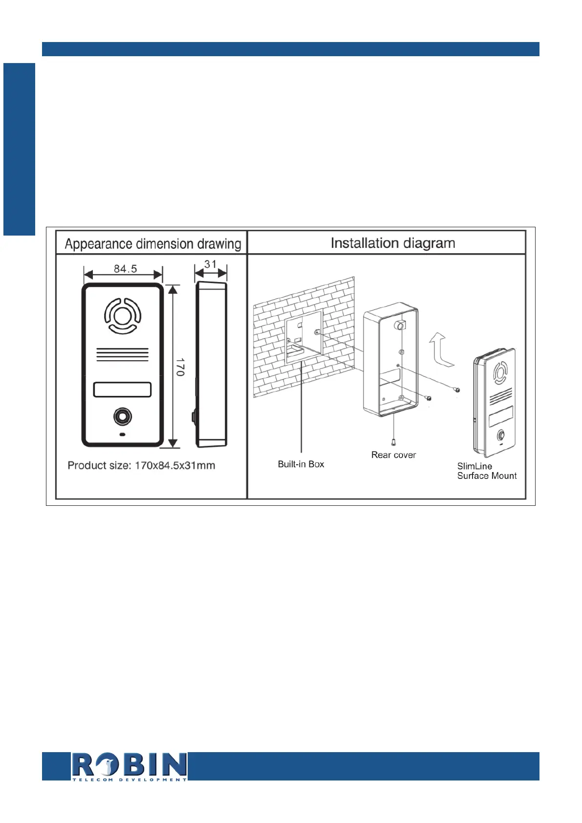
3.3 Surface mounting instructions
Follow the step-by-step plan described below for problem-free mounting of the Robin.
Step-by-step plan:
1. Mount a square built-in box in the wall (not supplied). Note: match the screws with the
holes of the rear cover to see if the square built-in box is compatible.
2. Feed the cables (Ethernet and (optional) door lock wires) through the built-in box.
3. Mount the rear cover to the built-in box. Note: Make sure the back of the rear cover is flush
(without any gaps) with the wall.
4. Connect the Ethernet cable to the Robin SlimLine.
5. Optional - connect the cable for operating the door switch to the supplied connector and
connect the connector to the Robin.
6. Position the Robin in- and upward in the rear cover.
7. Fix the device securely in place using the screw in the bottom of the rear cover.
I
Installation