Electrical connection
The electrical connection has to be carried out by a qualified electrician who is able to calculate the
required wire section and amperage of the fuses.
- confirm that the main voltage of your machine corresponds with the voltage in your workshop;
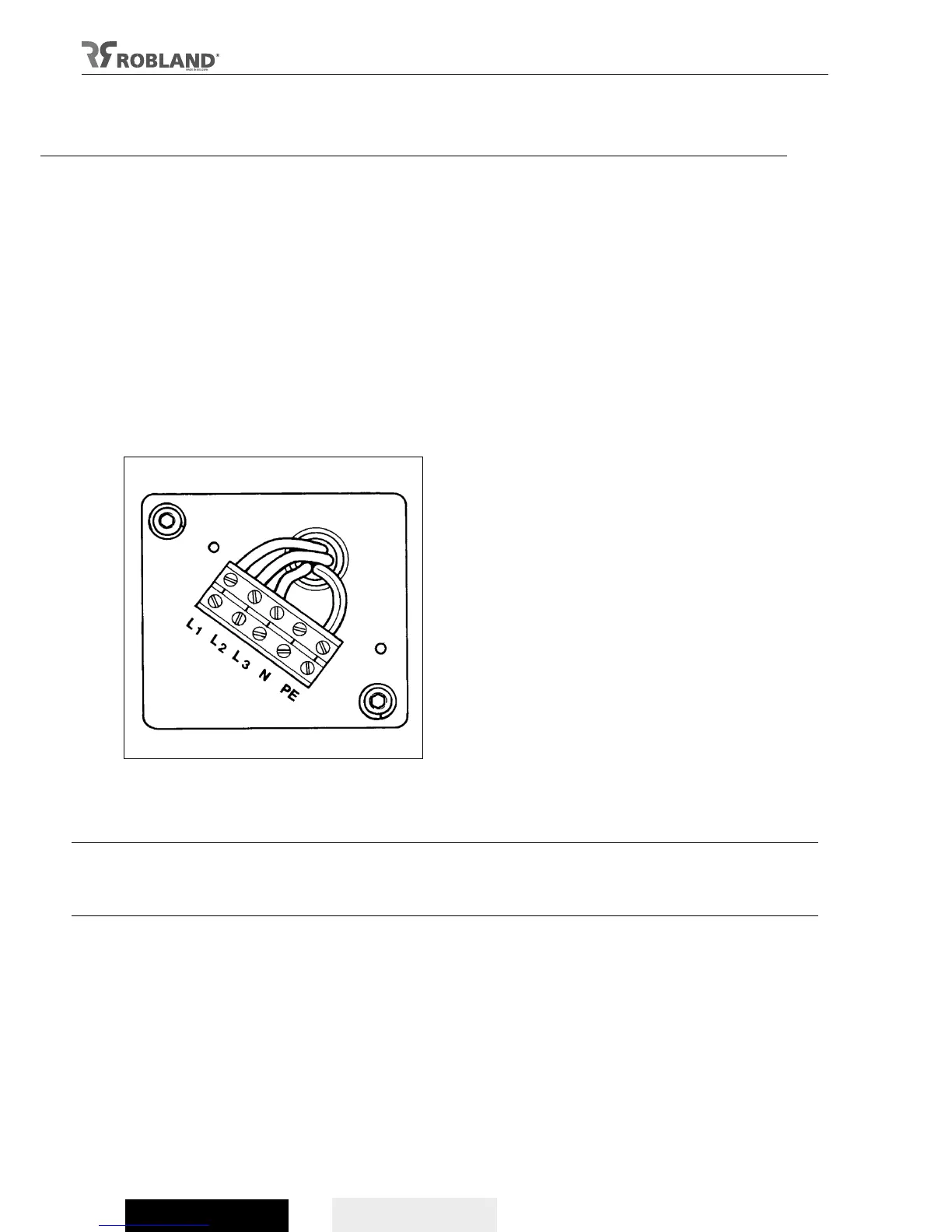
- the open the electrical components box at the back of the machine (fig 3);
- connect the 3 phases to the terminals marked L1, L2, L3 (fig 4);
- if there is a neutral conductor (blue) it has to be connected to the terminal N;
- connect the earth (green + yellow) to the terminal marked with the earth symbol;
- make sure the spindle runs free prior to starting up the motor.
Attention
- First, make sure that the spindle runs free and all necessary protective equipment is in place before
starting up.
- Should the direction of rotation be incorrect, the wires L1 and L2 must be exchanged. For safety,
this must be carried out without tools on the spindle. Check the direction of rotation of the motor. This
test should be carried out on the spindle-motor at 3000 RPM. The direction of rotation must be, seen
from above, anticlockwise.
Power supply
Electric potential motor spindle: 7,5pK (5,5kW S1) - option 10pK (7,5kW S1)
Electric potential motor up/down – front/rear : 0,1kW
Wire section connection wires: 2,5 mm
2
Nominal current: 11A (5,5 kW S1), 15A (7,5 kW S1)
Internal fuse head current: 3x230V – 25A of 3x400V – 16A
Connection: 3x230V + earth of 3x400V + earth
Frequency: 50 Hz