Changeable spindle (option)
The installation of the spindle arbor must be carried out in a clean way with the utmost care. It is
necessary to clean and oil slightly the spindle before mounting.
Proceed as follows: put switch 2 (fig 15) on “1”, push the lever (fig 17) on “B”. Next the spindle must be
turned manually to click into its lock.
It is necessary to wait until the spindle arrived at a complete halt before pushing down the locking lever
(fig 17). The spindle is free when the handle is put on “A”, locked when on “B”.
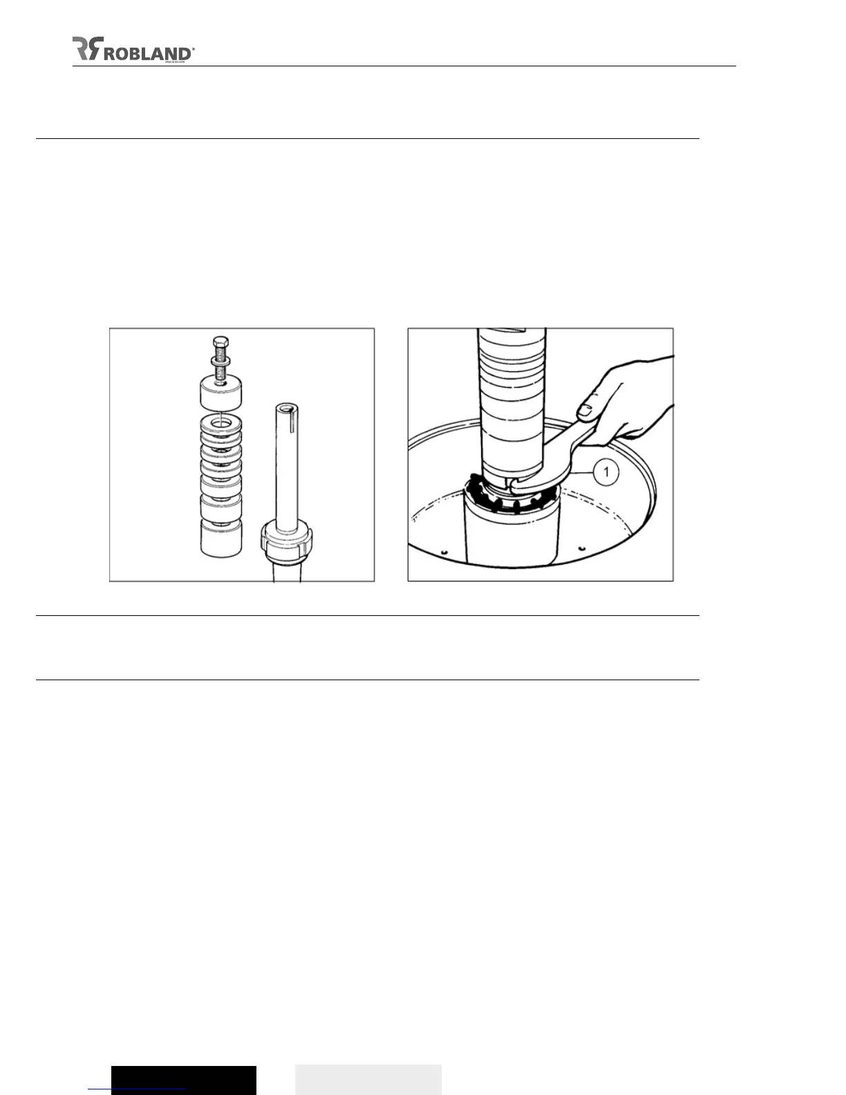
By turning the nut (fig 26.1) anticlockwise -right thread- with the hook-spanner, the spindle can be
loosened.
Always check the nut is well tightened.
Previous to starting up the machine, the brake release switch (fig 15.2) has to be put on “0” and the
lever (fig 16.1) on “A”. Check to make sure the spindle runs free.
Fig 25 Fig 26
Installation of tools
Always put the tool as low as possible on the spindle to minimize flexion and to obtain a major quality
of work. By means of rings with a different thickness a precise adjustment of the height can be
obtained in relation to the surface of the table. This can also be applied for the tools that are above the
table.
It is important that rings and arbor are perfectly clean. Tighten the bolt after mounting (fig 27.1).
Important
Please take care the top-ring with safety bolt is well installed into the spindle groove to avoid the tools
from loosening accidently.
Secure the spindle when changing or installing tools on the T120 and use spanner to loosen or
tighten, see “Spindle arbor lock” (pag 24).
On the T110i one uses a spanner No. 41 (fig. 28.1) to hold the spindle in position and an Allen key Nr.
10 (Fig. 28.2) to loosen or tighten the bolt at the top of the spindle (Fig. 28).