Adjustment of the spindle fence
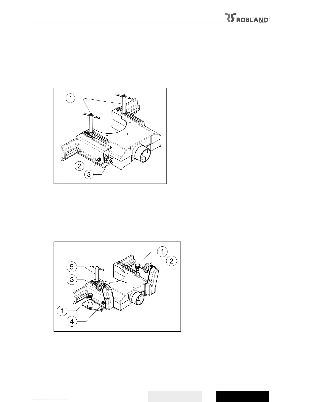
Basic version
- The body of the spindle fence is attached to the table with 2 bars (fig 9.1).
- The infeed fence can be arranged micrometric relative to the body of the fence by a screw
(fig 9.3).
- the position is locked by a knob (fig 9.2) on the side of the spindle fence.
Fig. 9
PRO version
- The body of the spindle fence is located on a guide plate and moves on linear guides.
- This plate is attached to the table by 2 locking pins (fig 10.1).
- The spindle fence is moved by using a hand-wheel (fig 10.2).
- Use the other hand-wheel to control the infeed fence (fig 10.3).
- Use the locking screw (fig 10.4) to lock the infeed guide in position.
- The body of the spindle fence is attached to the table with a bar (fig 10.5).
Fig.10