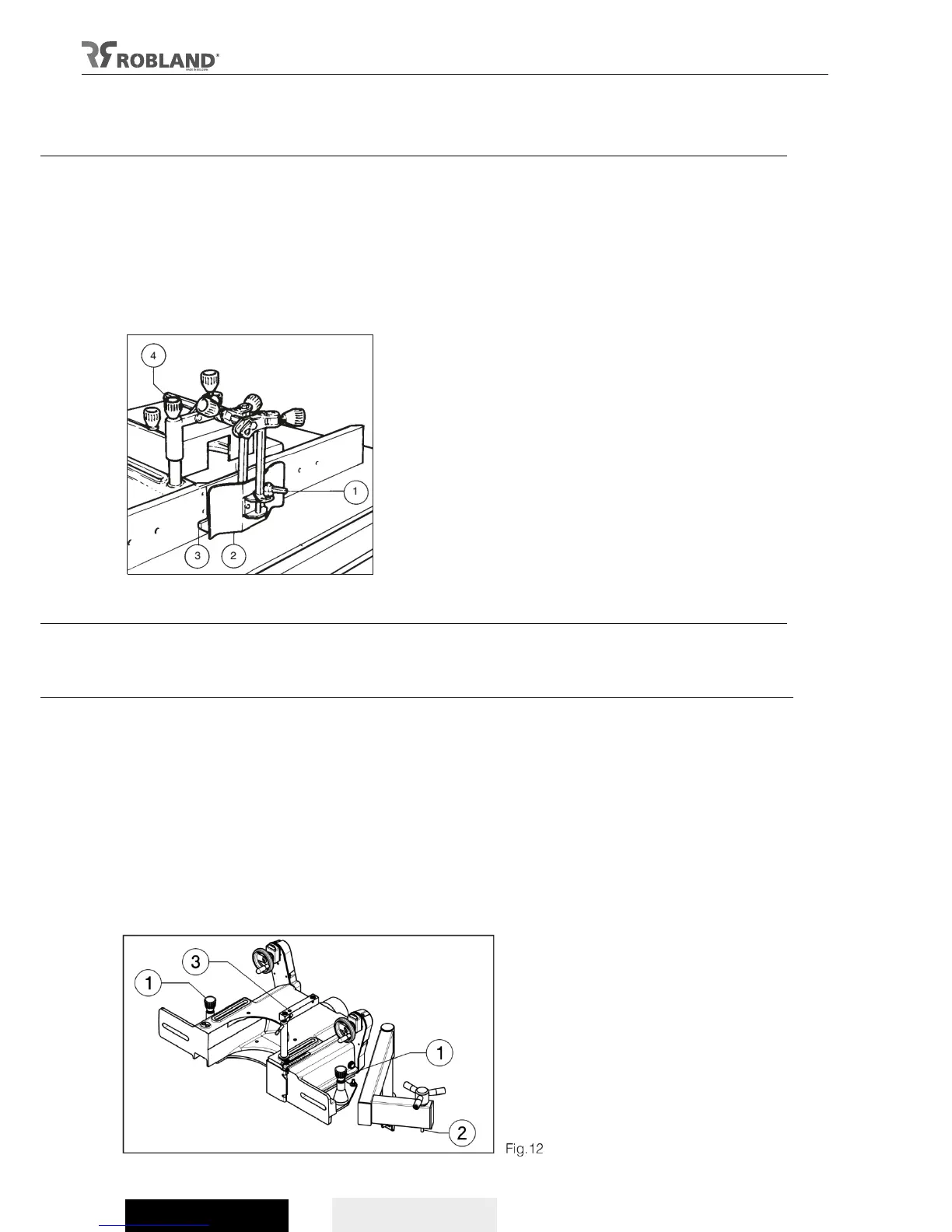
Spindle fence protections
Adjustments:
- Adjust the fences as close as possible to the tools and adjust the horizontal wood-pusher (fig 10.2) according to
the width of the piece of wood. Adjust the vertical wood-pusher (fig 10.3) according to the height of the piece of
wood that is machined, but make sure the wood is placed as close as possible to the fences.
- When the protection is placed correctly, the wood-pushers exert enough pressure and the wood can be put put
against the fences while it is supported between the clamps.
- It is advised to use a push-stick while working with the spindle protection.
- If only part of the wood is machined (see “operating instructions”) it is easier to push the piece of wood against
the stop when the horizontal wood-pusher screen is turned away.
- To remove the entire system from the vertical axle, it is needed to remove the knob..
Fig.11
Removing the spindle fence guide
- When the machine is equipped with a lift arm (option) the spindle fence guide can be removed easily.
- Move the protection forward on the guide plate and place the infeed guide backwards as far as possible. Proceed to
slide the superstructure forward to disassemble the guides.
Warning!
- When the machine is not equipped with a lift-arm (option), the removal of the spindle fence guide (weighting nearly
100 kg / 220 lb) is at your own risk and it is necessary to take adequate safety measures.
Important
- Start by unscrewing the 2 barring pens (fig 11.2) that hold the guiding plate when the lift arm is mounted.
- Then proceed to screw the lift arm (fig 11.2) onto the lifting block (fig 11.3).
- Once the spindle fence is completely lifted, the whole system can be pivoted away.
- To post the system back, just push the spindle fence back into place. Repair points are provided on the guiding
plate.