222 Rockwell Automation Publication 1766-UM001O-EN-P - September 2021
Appendix F MicroLogix 1400 Distributed Network Protocol
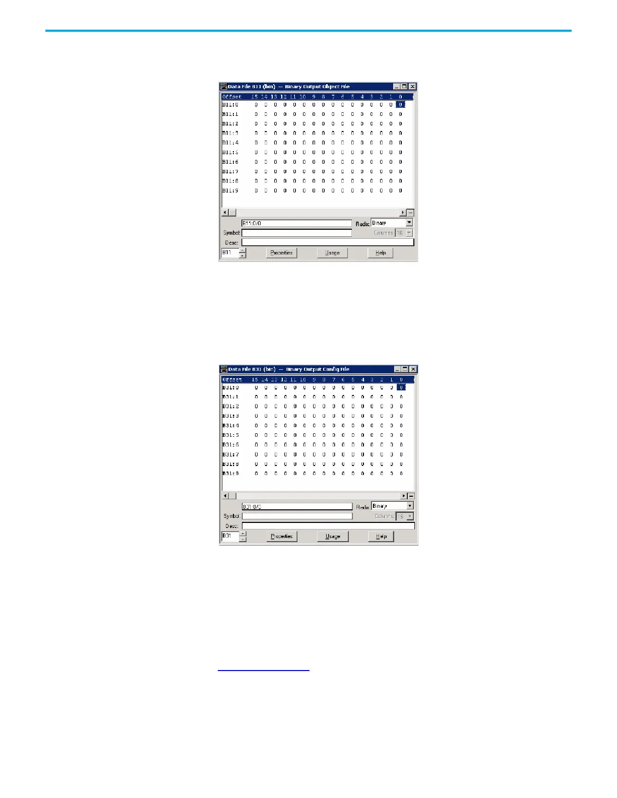
As an example, a Binary Output Object File is configured as shown below. This
file has 10 elements and 160 Binary Output points. Index 0 of the Binary
Output Object is B11:0/0, Index 1 is B11:0/1 and Index 159 is B11:9/15.
As an example, a Binary Output Config File shown below has 10 elements. Each
bit can be configured for Online information (if the corresponding point is
active or not, 0=offline, 1=online) of the Binary Output points. B31:0/0 is for
Index 0, B31:0/1 is for Index 1 and B31:9/15 is for Index 159. In the example
below, all bits are cleared and all of the points are in offline state.
If this bit is set, the Online bit in the status flag of each Binary Output points is
set when you read Binary Output Status objects.
Binary Command – Control relay output block (CROB)
The controller has three control models for Binary Output Control. They are
Activation model, Complementary latch model and Complementary two-
output model.
For the Complementary two-output model, two bits are required to control
this model in the Binary output object. The point index is different than in the
Activation or Complementary latch model. The point index varies as shown in
Table 27 on page 223
. The maximum number of Binary Output index for
Complementary two-output model is 2048.
 Loading...


