94 Rockwell Automation Publication 1766-UM001O-EN-P - September 2021
Chapter 5 LCD and Keypad
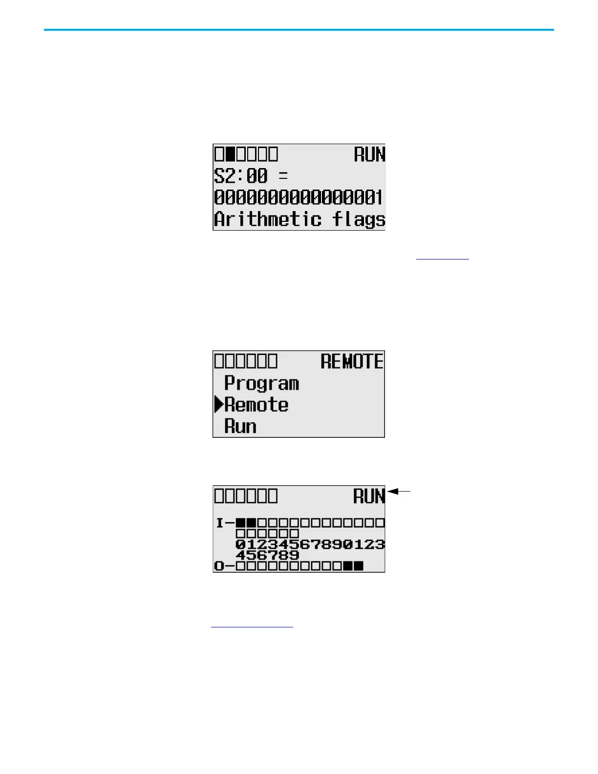
Monitor System Status Files
In this section, this assumption regarding the application program is made:
• The TUF element of the LCD Function File is set to 2. This specifies the
system status file S2 as the target file to monitor via the LCD.
The format string on the third line displays as decimal, hexadecimal, or binary
for each word element, depending on what each elements means.
For more information, see MicroLogix 1400 Programmable Controllers
Instruction Set Reference Manual, publication 1766-RM001
.
Mode Switch The MicroLogix 1400 controller provides the controller mode switch on the
LCD. The possible positions of the mode switch are PROGRAM, REMOTE, and
RUN. You can change mode switch position using the Mode Switch screen on
the LCD, as shown. In this example, the mode switch position is set to
REMOTE.
All the built-in LCD screens except the Boot Message screen display the current
mode switch position, at their top right portion, as shown. In this example, the
mode switch position is set to RUN.
Controller Modes
Table 13 on page 95 shows the possible controller modes when the mode switch
positions at PROGRAM, REMOTE, or RUN. For example, if the Mode Switch is
at RUN and you want to test a control program with running it for a single
scan, you have to first change mode switch position to REMOTE before you
run the control program in the remote test single scan mode with your
RSLogix 500 or RSLogix Micro programming software.
Current mode switch position
 Loading...


