344 Rockwell Automation Publication 2080-UM002N-EN-E - November 2022
Appendix G Connect to Networks using DF1
To configure the controller for a master station using message-based communication, place
the controller in program mode and follow the steps below in Connected Components
Workbench software.
Define the parameters shown in Table 95 when configuring a Micro800 controller as a master
station using message-based communication mode to talk to slave stations.
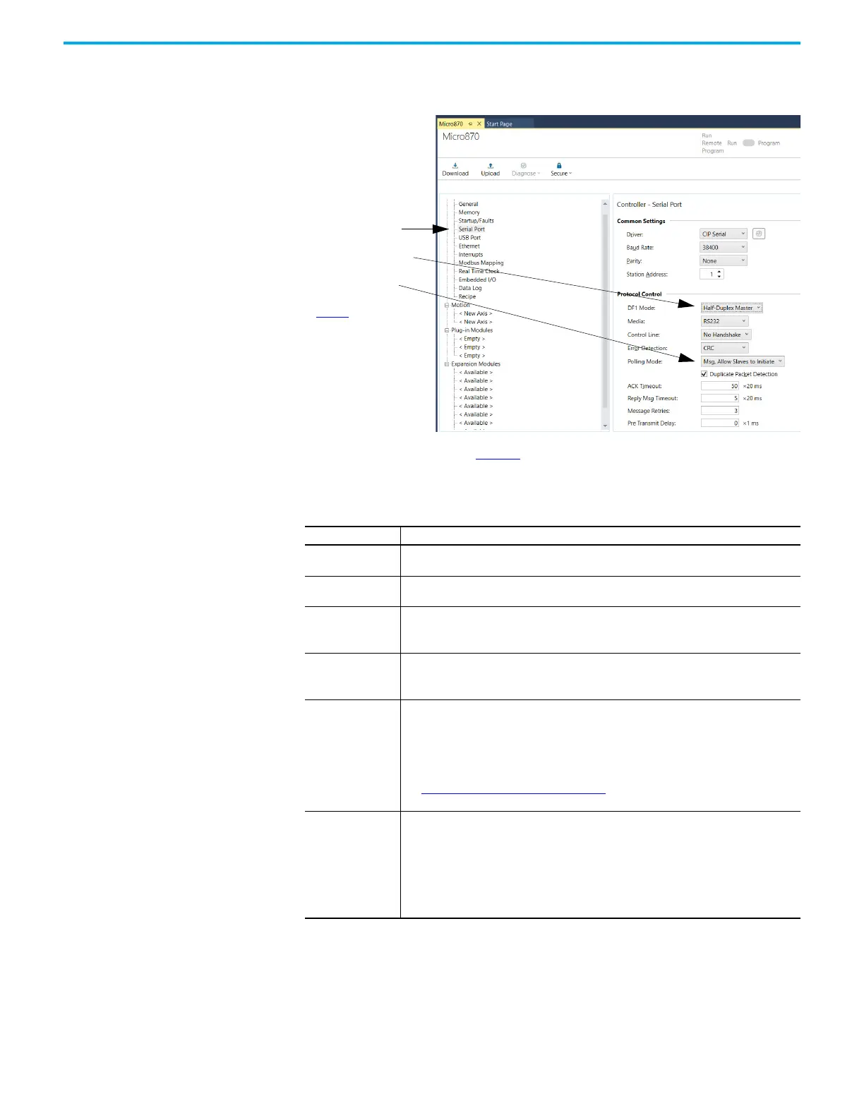
1. To bring up the configuration page, click
Serial Port.
2. On the Serial Port configuration page, select
Half-Duplex Master for your DF1 Mode.
3. Choose a Message-based Polling Mode.
4. Configure the rest of the communication
driver according to Table 95
.
Table 95 - Configure a Micro800 Controller as a Master Using Message-based
Communication Mode
Parameter Selections
Baud Rate
Select a communication rate that all devices in your system support. Configure all devices
in the system for the same communication rate.
Parity
Parity provides additional message packet error detection. To implement even parity
checking, choose Even. To implement no parity checking, choose None.
Node Address
A node address identifies the controller on the DF1 half-duplex link. Each station on a link
must have a unique address. Choose an address between 0
10
and 254
10.
Node address 255
10
is the broadcast address, and cannot be selected as a station’s individual address.
Media
Select the communication media for the DF1 protocol:
•RS-232
• RS-485 (only available when DF1 mode is Half-Duplex)
Control Line
This parameter defines the mode in which the driver operates. Choose a method
appropriate for your system’s configuration:
• If you are not using a modem, choose NO HANDSHAKE.
• If the master modem is full duplex, choose FULL-DUPLEX (RTS ALWAYS ON).
• If all the modems in the system are half-duplex, choose HALF-DUPLEX WITHOUT
CONTINUOUS CARRIER (RTS/CTS).
See Modem Control Line Operation
on page 338 for descriptions of control line operation
settings.
Error Detection
With this selection, you choose the how the controller checks the accuracy of each DF1
packet transmission.
BCC: This algorithm provides a medium level of data security. It cannot detect:
– transposition of bytes during transmission of a packet
– the insertion or deletion of data values of zero within a packet
CRC: This algorithm provides a higher level of data security.
Select an error detection method that all devices in your configuration can use.
When possible, choose CRC.
 Loading...