12 Rockwell Automation Publication 1756-UM021A-EN-P - September 2023
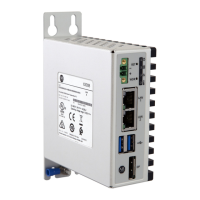
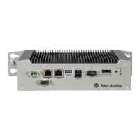
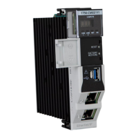
Chapter 1 ControlLogix Embedded Edge Compute Module
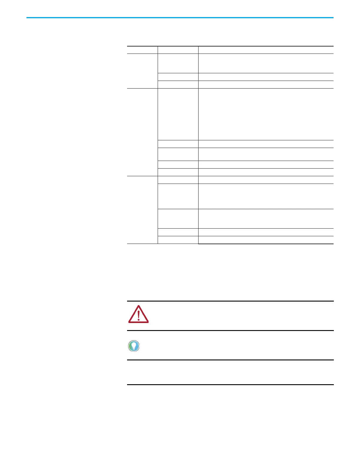
Status Indicators The module uses a 4-character display and status indicators to show the module state at any
point in time.
Connection Options The module has USB and Ethernet ports.
USB 3.0 Port
You use the USB port to connect peripherals to the module. The USB port supports the use of a
USB hub. FAT32 and exFAT file systems are supported.
Indicator State Description
LINK 1
LINK 2
Off
No activity. One of these conditions exists:
• The device is not connected to a network.
• The port is administratively disabled.
Steady green The device is connected to a network but is not actively communicating.
Flashing green The device is actively communicating on a network.
NET
Off
One of these conditions exists:
• The module is not powered.
– Verify that there is chassis power.
– Verify that the module is completely inserted into the chassis and
backplane.
– Make sure that the module has been configured.
• The module is powered but does not have an IP address. Assign an IP
address to the module.
• The port is administratively disabled.
Flashing green The module has an IP address, but no active connections are established.
Steady green
The module has an IP address and at least one established active
connection.
Steady red Duplicate IP address or invalid configuration.
Flashing Green/Red The module is performing its power-up testing.
OK
Off No power is applied to the module.
Flashing red
One of the following is true:
• The device has a recoverable fault.
• The device firmware is being updated.
• Factory reset is in progress.
Steady red
One of the following is true:
• The module is powered, but is inoperable.
• The module has a major nonrecoverable fault.
Flashing green The module is booting.
Steady green The module is operating normally and the boot phase is completed.
WARNING: If you connect or disconnect the USB cable with power applied to this
module or any device on the USB network, an electric arc can occur. This can
cause an explosion in hazardous location installations.
Be sure that power is removed or the area is nonhazardous before proceeding.
We recommend that you connect any peripherals to the USB port before you power
up the module.
IMPORTANT When fully inserted, the USB connectors lock into the USB port.
Before you remove a USB connector, press the silver release tab on the
left side of the USB port.
 Loading...