Rockwell Automation Publication 2198-UM001D-EN-P - May 2014 155
Removing and Replacing Servo Drives Chapter 8
Remove the Servo Drive
You can remove single-axis drives from the panel or any single drive from a multi-
axis configuration by using the same procedure.
Follow these steps to remove Kinetix 5500 servo drives from the panel.
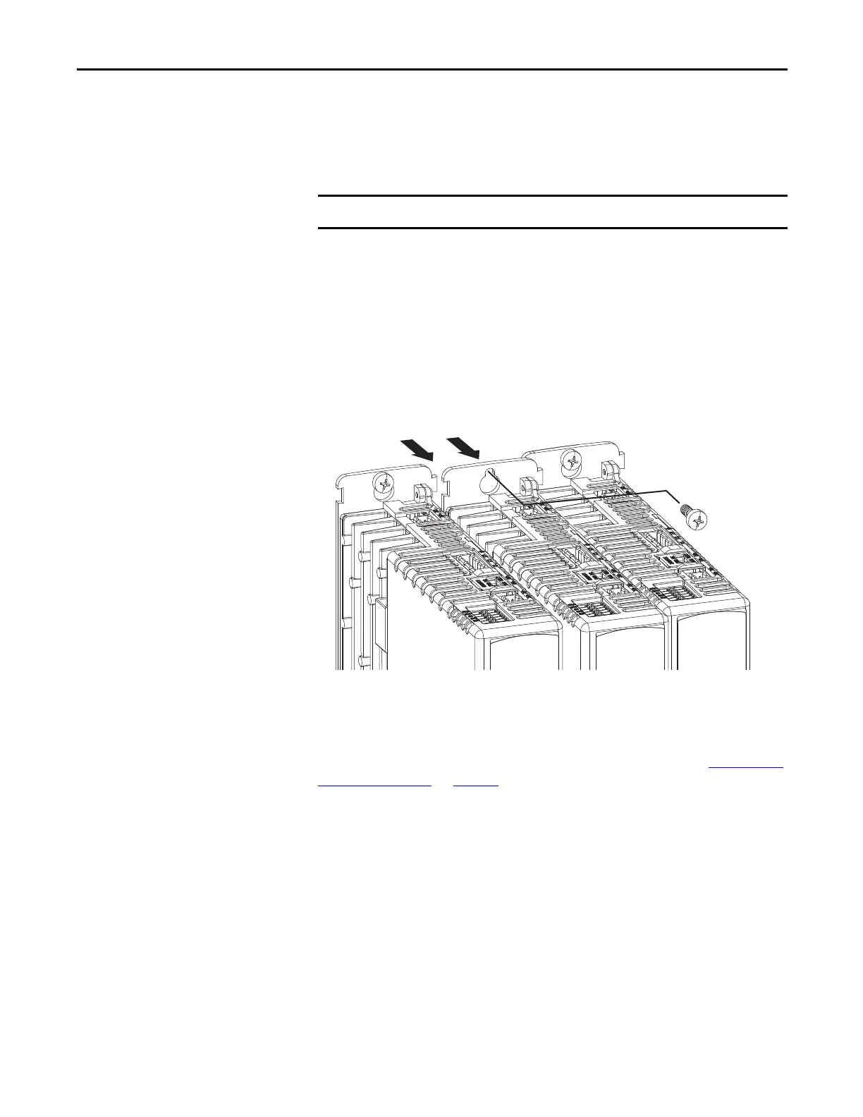
1. Remove the top and bottom screws of the drive to remove.
Frame 1 and 2 drives have one top and bottom screw. Frame 3 drives have
two top and bottom screws.
2. Grasp the top and bottom of the drive with both hands and pull the drive
straight out and away from the panel, clearing the zero-stack mounting
tabs and cutouts.
Replace the Servo Drive
To replace the servo drive, reverse the steps shown above or refer to Mount Your
Kinetix 5500 Drive on page 56:
• Torque mounting, shield clamp, and ground screws to 2.0 N•m
(17.7 lb•in) max.
• Reconnect the feedback connector kit and torque the mounting screws to
0.4 N•m (3.5 lb•in) max.
This procedure applies to any 2198-Hxxx-ERSx drive in any configuration.
Kinetix 5500 Servo Drives
(removing middle drive)
Top Screws
(bottom screws not shown)

 Loading...


