78 Rockwell Automation Publication 2198-UM001D-EN-P - May 2014
Chapter 5 Connecting the Kinetix 5500 Drive System
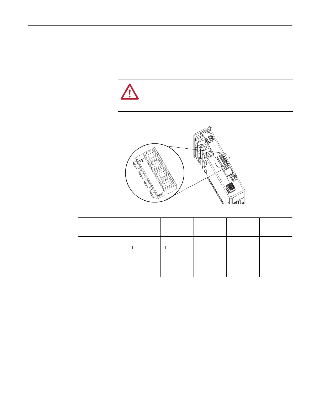
Wire the Input Power Connector
The input power (IPD) connector requires 195…528V AC (single-phase or
three-phase) for mains input power. The single-axis connector ships with the
drive, shared-bus connector kits are purchased separately.
Figure 43 - IPD Connector Wiring - Single Axis
Table 34 - Single-axis IPD Connector Wiring Specifications
ATTENTION: Make sure the input power connections are correct when wiring
the IPD connector plug or input wiring connector and that the plug/connector is
fully engaged in the drive connector. Incorrect wiring/polarity or loose wiring
can cause explosion or damage to equipment.
L3
L2
L1
Remove
For DC
Bus Only
Kinetix 5500 Drive
Top View
Input Power (IPD)
Connector Plug
Kinetix 5500 Drive
Cat. No.
Pin Signal
Recommended
Wire Size
mm
2
(AWG)
Strip Length
mm (in.)
Torque Value
N•m (lb•in)
2198-H003-ERSx
2198-H008-ERSx
2198-H015-ERSx
2198-H025-ERSx
2198-H040-ERSx
1.5…4
(16…12)
8.0 (0.31)
0.5…0.6
(4.4…5.3)
2198-H070-ERSx
1.5…6
(16…10)
10.0 (0.39)

 Loading...


