Rockwell Automation Publication 2198-UM001D-EN-P - May 2014 47
Mounting the Kinetix 5500 Drive System Chapter 3
Shared-bus Connection System
The shared-bus connection system is used to extend the mains AC input, 24V
control input, and the DC bus power from drive-to-drive in shared-bus multi-
axis configurations.
The connection system is comprised of three components:
• Input wiring connectors that plug into the leftmost drive and receive input
wiring for mains AC and 24V DC.
• AC bus, DC bus, and 24V DC T-connectors that plug into the drives
downstream from the first where AC, DC, and/or 24V control power is
shared. DC bus T-connectors also plug into the first drive where DC bus
power is shared.
• Bus bars that connect between drives to extend the mains AC bus, DC bus,
and 24V DC control power from drive-to-drive.
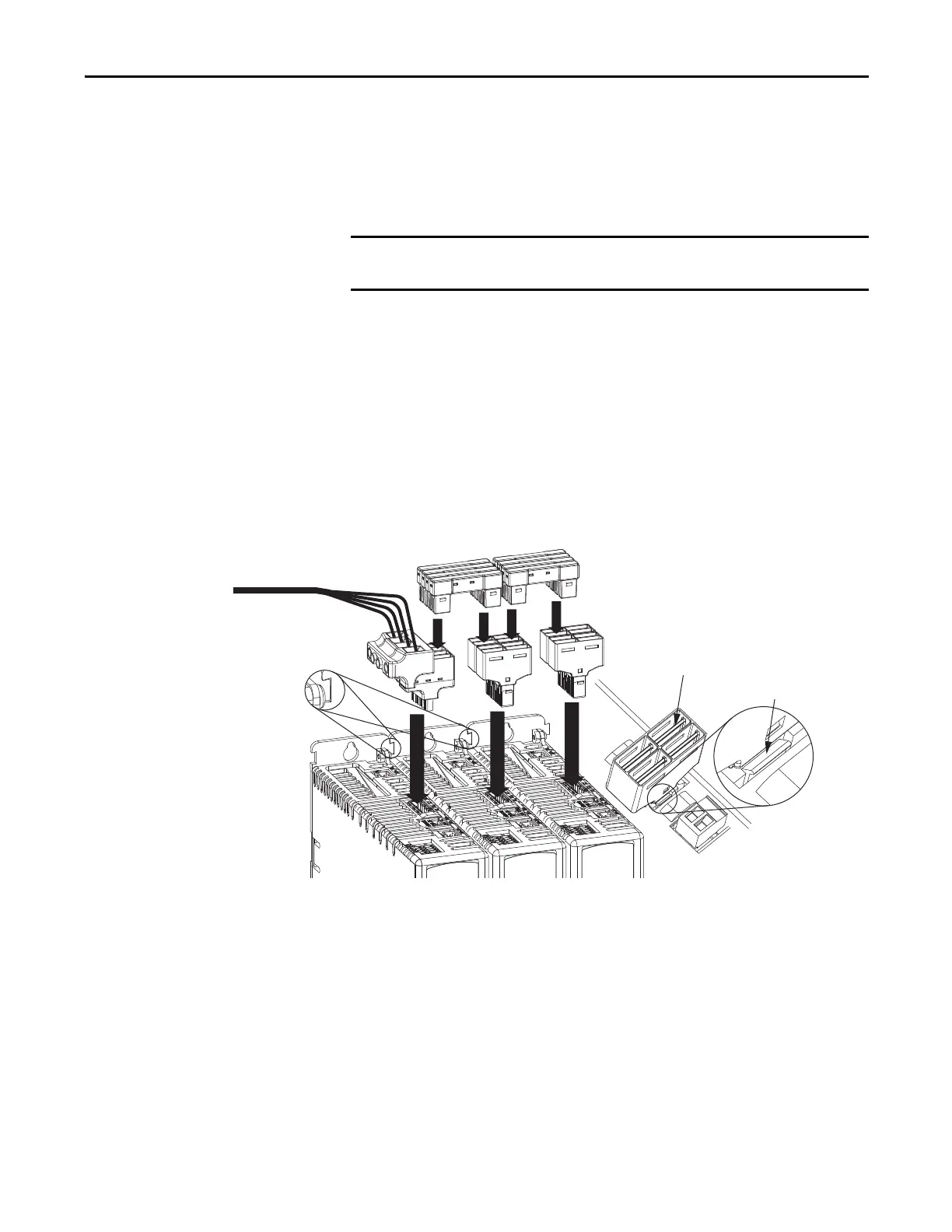
Figure 21 - Connection System Example
(1) Due to the higher amp rating of frame 3 drives, input wiring connectors for frame 3 drives (catalog number 2198-H070-ADP-IN) are
slightly larger than connectors for frame 1 and 2 drives (catalog number 2198-H040-ADP-IN).
(2) Due to the extra width of frame 3 drives, bus-bar connectors between frame 3 drives are slightly longer (85 mm) than connectors
between frame 3, frame 2, and frame 1 drives (55 mm).
(3) DC bus T-connectors latch on both sides when inserted into the drive. To remove the DC bus T-connector, at least one latch must be
pried away with a non-conductive probe.
The three components assemble from left to right across the drive system.
1. Attach wiring to input wiring connectors.
2. Insert input wiring connectors and T-connectors into the appropriate
drive connectors.
3. Insert bus-bars to connect between wiring connectors and T-connectors.
When the shared-bus connection system is used, the zero-stack tab and
cutout must be engaged between adjacent drives.
Input Wiring Connector
(1)
(mains AC input shown)
AC T-connectors
Bus-bar Connectors
(2)
(AC bus-bars shown)
Input Wiring
(AC input wiring is shown)
Zero-stack Tab
and Cutout Engaged
2198-Hxxx-ERSx Drive System (top view)
Frame 2 drives are shown.
Drive with largest amp rating must be
leftmost drive.
DC Bus Connector Latch
DC Bus T-connector
(3)

 Loading...


